Table of Contents
Advertisement
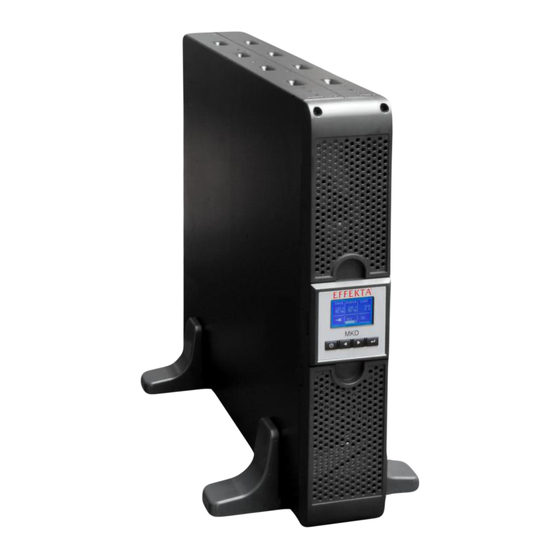
UPS
Uninterruptable Power Supply
MKD 700 – 3000 VA RT (XL)
Operating Manual V 2.6
Device:
MKD 700 RT
MKD 1000 RT
MKD 1500 RT
MKD 2000 RT
MKD 3000 RT
MKD 700 RT XL
MKD 1000 RT XL
MKD 1500 RT XL
MKD 2000 RT XL
MKD 3000 RT XL
Translation of original operating manual
Article number:
ACX11MKT70000000
ACX11MKT1K000000
ACX11MKT1K500000
ACX11MKT2K000000
ACX11MKT3K000000
ACX11MKT70000RXL
ACX11MKT1K000RXL
ACX11MKT1K500RXL
ACX11MKT2K000RXL
ACX11MKT3K000RXL
Advertisement
Table of Contents


Need help?
Do you have a question about the MKD 700 RT and is the answer not in the manual?
Questions and answers