
Related Manuals for Effekta MH6000


Summary of Contents for Effekta MH6000
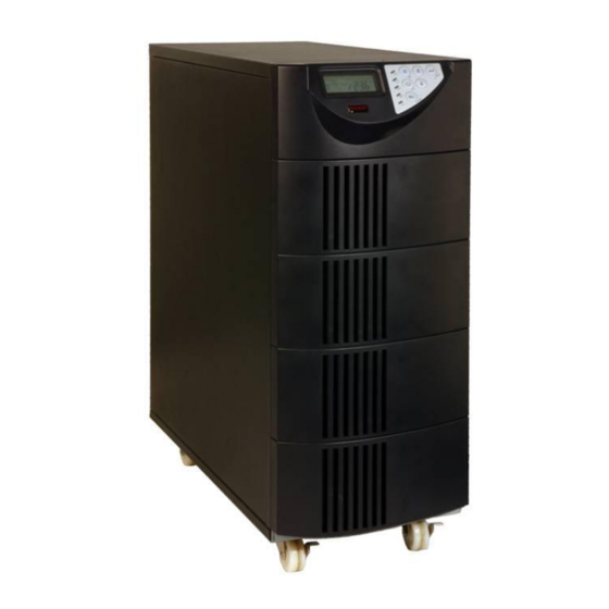
- Page 1 Uninterruptible Power Supply MH 6000 Manual Item no.: 03A / 06000MH-000 July 08...
- Page 2 Installation Connection Operation Application of batteries Maintenance, service and errors Introduction System description MH6000 – description Display- and handling elements on the front side 6.1.1 Handling elements on the UPS 6.1.2 Symbols on the LCD-display Display on the back side...
-
Page 3: Table Of Contents
MH6000 Manual Switch-off Maintenance bypass-mode Troubleshooting 10.1 Troubleshooting 10.2 Failure codes Software Maintenance and service 12.1 Measurement of the autonomy time 12.2 Exchange of the batteries 12.3 Service-protocol 12.4 Service - Hotline: 12.5 Maintenance and service contracts Technical characteristics 13.1 Specifications 13.2... -
Page 4: Safety Instruction
All used brand marks are property of the owner. ® EFFEKTA is a registered brand mark of the company EFFEKTA Regeltechnik GmbH Technical and optical deviations as well as errors and omissions excepted (E.&O.E.) Page 4 of 51 MH Series... -
Page 5: Warranty Conditions
MH6000 Manual 2 Warranty conditions The receipt quittance is evidence for the initial purchase and should be retained, because it is necessary for guarantee services. If the product is passed on to another user, the warranty will still be valid until the end of the guarantee period. - Page 6 2.1 Liability limitation Claim of damages are excluded only in case of intention or grossy negligence of the EFFEKTA GmbH or its employees. The liability according to the product liability law remains unaffected. We are in any circumstances not liable for: Claims of other parties due to loss or damage.
- Page 7 MH6000 Manual 3 Safety 3.1 General Safety Instructions Read the manual attentively and respect the safety instructions which are mentioned in this chapter before doing taking further steps (transport, storage, connection, setting-up, etc.). As UPS-systems are working with voltage and have got corresponding internal or external energy storages (batteries with high capacity), the instructions in this chapter are very important for all users and the whole stuff.
- Page 8 MH6000 Manual This UPS provides electronically units in offices, telecommunication systems, process controls, medical and safety applications. Not authorized persons are not allowed to install the UPS in the following fields. 1. Medical applications for the protection of human life.
- Page 9 MH6000 Manual 3.2 Transport and storage The UPS has to be transported in its original packaging, also in case of moves or returns. Do not transport the unit headlong. Protect the position during transport and pay attention to the centre of mass.
- Page 10 MH6000 Manual Do not connect the UPS with machines which could overload it (e.g. laser printer). The sum of earth fault currents of all with the UPS connected machines should not be higher than 3.5mA. Keep the access lines short and always connect them correctly. Dagers as to stumble, to squeeze, etc.
- Page 11 MH6000 Manual 3.6 Application of batteries Attention – risk of electric shocks and burns. Batteries can cause electric shocks and have high short-circuit currents, which also can cause burns. Unauthorized persons should be kept away from batteries. Keep devices which heat away from the batteries and do not throw them into fire.
- Page 12 MH6000 Manual 4 Introduction This manual should inform you essentially about one-phase online UPS- systems and its functioning, the application of several functions and about what to do in case of service disturbances. Furthermore this manual includes applications for transport and storage as well as handling and installation of the UPS-systems.
-
Page 13: System Description
MH6000 Manual 5 System description The UPS is in a non-stop service with double conversion mode. It conditions the current circuit and supplies an uninterruptible, undisturbed and one-phase voltage for critical machines. During supplying the connected machines, it keeps its internal batteries in a charged condition. In case of a power failure or a power disturbance, the UPS supplies also uninterrupted and clean voltage at its output. - Page 14 MH6000 Manual 6 MH6000 – description In this chapter you will be confronted with the corresponding machine elements, get instructions for the handling and get information concerning the connections of the UPS. 6.1 Display- and handling elements on the front side On the front side are all handling and display elements for the normal service.
- Page 15 MH6000 Manual LCD- display The green LED signs indicate that the UPS can work with redundancy mode. Constant glowing of the LED indicates that the input voltage is within the defined window. The LED jitters when input voltage is within the still tolerated window.
- Page 16 MH6000 Manual 6.1.2 Symbols on the LCD-display Symbol Description Source of supply or bypass LINE low battery battery fault UPS overcharge UPS works in the defined mode* A blackout transfer has appeared at the output of the UPS. Bypass input out of the tolerance, UPS can not switch to bypass, bypass fault in the eco-mode.
- Page 17 MH6000 Manual Next page. To log out /in special functions. Enter or confirm again. LED power supply ok LED bypass supply ok UPS in redundancy mode. UPS in eco-working mode. LED UPS fault Er01 Failure codes Page 17 of 51...
- Page 18 MH6000 Manual 6.2 Display on the back side Fig. 3: back side view Danger! All the connections on the back side (except of: RS232-interface, SNMP adapter) have got circuit potential when attached. Also when uncoupled dangerous voltage capacity in possible in the inside of the unit.
- Page 19 MH6000 Manual RS232 port Reserved for parallel function CAN Bus connection for parallel system Client's option plug-in position 1 (relays card) Client's option plug-in position 2 (SNMP-card) External battery connection Connection for an external battery charger Mains automatic circuit breaker...
-
Page 20: Storage And Unpacking
MH6000 Manual 7 Storage and unpacking 7.1 Storage of the UPS If the unit is not going to be installed immediately, follow those instructions: Store and keep the UPS always in its original packaging. Suggested environmental temperature for storage is: +5°C...+30°C. -
Page 21: Installation And Connection Of The Ups
MH6000 Manual 8 Installation and connection of the UPS All instructions for environmental and service conditions have to be complied to guarantee the perfect function of the UPS. 8.1 Choice of the fitting position To avoid damages and to increase service life of the UPS you have to choose a convenient environment for the installation of the unit. - Page 22 MH6000 Manual 8.2 Description of the terminal block Fig. 4: terminal block L11-N1: input terminal blocks bypass supply L12-N1: input terminal block main supply G1: protective terminal block input L21、N21、L22、N22: UPS output terminal block. G2: protective terminal block output Notes: 1.
- Page 23 MH6000 Manual AC-systems 200/100 V, 220/110 V, 230V/115 V or 240/120 V, you can connect as follows. 220Vac AC-systems 240/208/120 V, you can connect as follows. 208Vac 120Va 120Va 240Vac 8.3 Connection of the UPS Follow the following instructions and the fig. 5 when connecting the UPS: Fig.
- Page 24 MH6000 Manual the protective grounding of the connected machines is guaranteed; or if the connected machine is protected separately from over current or error current and additionally grounded; If the UPS is in a emergency power-off mode, you have to ensure that in case of activation, the UPS output is not without current.
- Page 25 MH6000 Manual 8.4.1 Interface RS232 The following chart indicates the modulation of RS232 interfaces: Baud-Rate 2400 bps Fig. 6: RS232 interface Date length 8 Bits modulations Stop bit 1 Bit Parity For connection just use the cords which are described under the chapter „accessories”.
- Page 26 MH6000 Manual 8.4.2 Interface-card (options) 8.4.2.1 DCE- card (relay interface) Fig. 8: DCE- card, relay card The pin configuration of the 10-pin-terminal-block: Pin: Description; Fig. 9: pin configuration of UPS bypass mode the contact- Mains ok (NO) interface Mains ok (NC)
- Page 27 MH6000 Manual Fitting position: JUST plug-in position 2 (see fig. 3 [D]) Adjusted flat cable: cable A or cable B For installation see chapter Fehler! Verweisquelle konnte nicht gefunden werden. 8.4.2.2 SNMP cards SNMP/WEB card Fig. 10: SNMP/WEB card With regard to the installation refer to the description attached to the card.
- Page 28 MH6000 Manual 8.4.3 Installation of optional interfaces The installed flat cable has to be the same as the following indicated cable. fig. 11: flat cable for optional interface-cards Follow those instructions for the installation of the hardware. Take the cover away of the slot.
- Page 29 MH6000 Manual 9 Handling of your UPS-system The service of this system is characterized by several service types and indications. 9.1 Setting-up in the normal mode 1. Open the cover of the terminal block at the back side. Before installation, ensure that protective grounding is correct.
- Page 30 MH6000 Manual 7. Now the UPS is again in the self-test mode, the LCD-display changes from drawing C to drawing D an stays about 4 seconds in battery service. If the self-test is successful, the drawing changes from E1 to F.
- Page 31 MH6000 Manual 9.2 Setting-up in the battery mode (cold starting) 1. Ensure that the UPS that you have installed has got more that 1 set (20 pieces) 12 V/ 7 AH batteries. 2. Push the switch-on button of the UPS for about 3 seconds to activate the UPS.
- Page 32 MH6000 Manual * indicates voltage, which comes from the bypass input. * indicates frequency from the supplying input. * indicates frequency from the bypass input. * indicates UPS voltage output. * indicates UPS output frequency. Page 32 of 51 MH Series...
- Page 33 MH6000 Manual * indicates UPS output load (%). * indicates battery voltage. * indicates UPS internal temperature. 9.4 UPS requirements and special functions 1. After the complete start of the UPS, push the button , to change the LCD-display to drawing Q1.
- Page 34 MH6000 Manual 2. To check the UPS installations push the button . The LCD-displays changes over to drawing Q1 (buzzer) -> drawing R! (self test) -> drawing S1 (tolerance window for the bypass voltage) -> drawing T (output frequency synchronization tolerance window) -> drawing U (inverter output voltage) ->...
- Page 35 MH6000 Manual * indicates, that the frequency tolerance window is at +/-3Hz. * indicates the inverter of the output voltage. * indicates, that the UPS is in normal mode „Normalmodus. * indicates, that teh UPS is in eco-mode „Ökomodus”. * indicates, that the UPS is in „CVCF 50 Hz Modus“ mode.
- Page 36 MH6000 Manual * indicates, that the UPS is in „CVCF 60 Hz Modus“ mode. * indicates the installation of the output voltage in % from 0% up to 3% or from –0% up to –3%. * indicates the UPS number of identification.
- Page 37 MH6000 Manual 9.5 UPS presets and their possibilities 1. Ensure, that the UPS is not yet switched-on „Ein“. Push the switch-on button and scroll with button for about 3 seconds down, the buzzer resounds two times, the LCD- display indicates drawing Q1, the UPS is now in installation mode.
-
Page 38: Switch-Off
MH6000 Manual * indicates, that the UPS is blocked. 4. Switch the automatic breaker of the supplying input off. 5. Your settings are finished. 9.6 UPS is switched-off due to unknown reasons - troubleshooting 1. If a failure occurs, the UPS locks itself into out „AUS“position, as in drawing AA and the LCD-display will indicate an error message. -
Page 39: Troubleshooting
MH6000 Manual Before starting this procedure, you should store all data. Also inform all involved users. !! Attention!! An incorrect changeover of the bypass-switch can cause damage of the UPS or of the connected machines. The change over instructions has to be respected in the right sequence. -
Page 40: Troubleshooting
MH6000 Manual 10.1 Troubleshooting If failures occur during the UPS service, you can check the following points: 1. Is the connection of input and output correctly? 2. Is the input voltage within the input tolerance window of the UPS? If there are still problems, follow the below mentioned schedule. If you can not solve the problem, contact your local supplier. - Page 41 MH6000 Manual Problem Check the element Solution: The red LED at the UPS Check the failure code 1. Check if the connection of glows up. which is indicated on the battery is correct, load the LCD-display. the batteries again for 8 hours to see if the UPS 1.
-
Page 42: Failure Codes
MH6000 Manual 10.2 Failure codes The following schedule illustrates the existing failure codes of the UPS: Code Status 1. Phase BUS capacitor pre-voltage is faulty (<90% battery voltage Er01 after 30 seconds ) or battery fuse failed (relays soft start on). - Page 43 MH6000 Manual Er26 PFC over current. Er27 No use (occupied). Er28 More than 2 minutes 120% overload in the bypass. Bypass scr off. Er29 The charger overloads the battery (>300Vdc). CEr1 Supplying voltage is not in allowed limit. CEr2 Bypass voltage is not in allowed limit.
-
Page 44: Software
MH6000 Manual 11 Software Installations and service conditions of the UPS can be detected and handled by an adequate software package. The software packages are available over the producer / supplier or over the mentioned service-hotline (chapter „Service“). There you get necessary information about adequate software packages with regard to your application and UPS. -
Page 45: Maintenance And Service
MH6000 Manual 12 Maintenance and service It can be seen as fact that the UPS has got a long service life and an undisturbed function, with regard to a minimum maintenance. But the liability of the UPS depends of the environmental conditions. Temperature and humidity in the environment of the UPS have to be within the indicated limit. - Page 46 MH6000 Manual Just specialized staff is allowed to do works on the battery pack. This staff must have professional experience with regard to batteries. Notice that there is still high voltage after disconnection, for example voltage in the battery pack, loading voltage of net capacitors. Precaution regarding to electric shocks have to be respected.
-
Page 47: Service-Protocol
MH6000 Manual 12.3 Service-protocol Please always inscribe hereunder every maintenance or service work on the UPS. Date: Activities: Responsible: Page 47 of 51 MH Series... -
Page 48: Service - Hotline
12.5 Maintenance and service contracts EFFEKTA Regeltechnik GmbH offerst adequate maintenance and service contracts to guarantee the best liability and availability of the UPS. Furthermore we can support you within a maintenance and service contract in following areas: Regular examination of the unit, especially of the batteries as well as a punctually exchange an disposal of the batteries;... -
Page 49: Technical Characteristics
MH6000 Manual 13 Technical characteristics 13.1 Specifications Model: MH6000 Capacity: 6000 VA / 4200 W UPS input: phases 1 external conductor + neutral conductor voltage window 160 -280 V AC nominal frequency 50 / 60 Hz 45 – 65 Hz... -
Page 50: Accessories
Dimensions: w x d x h [mm] 748 x 290 x 645 mm 13.2 Accessories In the following schedule are components which are tested and approved especially for this UPS by EFFEKTA Regeltechnik GmbH: Accessory: Function: Item number: Software package... -
Page 51: Wearing Parts
92/31/EG – complement to EMC guideline 89/336/EEC Standards: EN 50091-1 EN 50091-2 An EU declaration of conformity for CE-labeled products may be optionally on request from the following address: EFFEKTA Regeltechnik GmbH Rheinwaldstr. 34 78628 Rottweil GERMANY Phone: 0049 / (0) 741–17451-0 Page 51 of 51...
Need help?
Do you have a question about the MH6000 and is the answer not in the manual?
Questions and answers