Table of Contents
Advertisement
Quick Links
Advertisement
Table of Contents

Subscribe to Our Youtube Channel
Related Manuals for Plus COPY BOARD M-115


Summary of Contents for Plus COPY BOARD M-115
- Page 1 COPY BOARD M-115 SERVICE MANUAL...
-
Page 2: Table Of Contents
CONTENTS 1.COMPLIANCE OF SAFE REPAIR ........ 1 6. ADJUSTMENT .............. 20 1-1. Cautions during Product Displacement ..... 1 6-1. CCD Adjustment ............20 1-2. Cautions during disassembling and assembling ..1 6-2. Calibration ..............25 2.SPECIFICATIONS ............2 6-3. Tension Adjustment of Timing Belt ......26 2-1.Product Specifications .......... -
Page 3: Compliance Of Safe Repair
1. COMPLIANCE OF SAFE REPAIR Be sure to read this Service Manual before providing services. In the PLUS Copyboard, full consideration is taken to ensure the safety for a fire, electric shock, injury, harmful radiation, and substance. Therefore, observe the notice described in this Service Manual so that the safety is kept when providing services. Moreover, be sure to observe the notice described in the User’s Manual. -
Page 4: Specifications
2. SPECIFICATIONS 2-1. Product Specifications Standard (M-115) BOARD TYPE (Model name) Self-standing (T-shaped legs), or wall mounting Form Installation method External dimensions W1470 D700 H1970 (Max)* (T-shaped legs* 1) 33.0 kg* (excluding printer) Main unit weight 9.6 kg T-shaped legs weight H920 W1300 mm Board... -
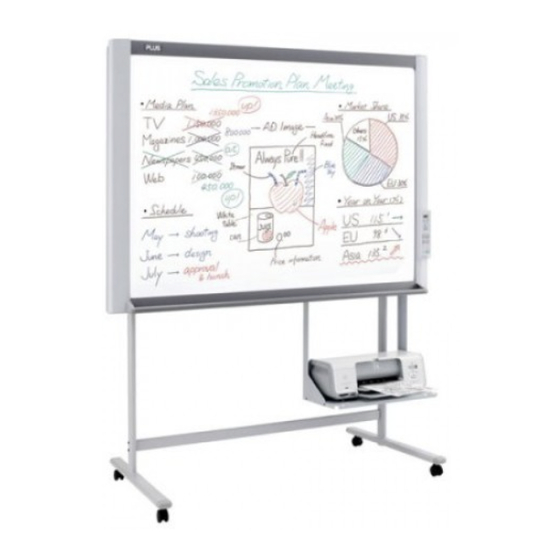
Page 5: Location Of Parts And Controls
SPECIFICATIONS 2-2. Location of Parts and Controls Front panel of main unit Frame Cover Copyboard Sheet Figures or characters are drawn in this sheet using a dedicated marker. Operation Panel Tray Printer Tray A printer is put in this printer stand. (See Assembling, Installation manual.) Stand * Stand holding this unit. - Page 6 SPECIFICATIONS Back panel of main unit DC input connector Connect the DC side of an AC power adapter to the DC input terminal. (Connect only the AC power adapter exclusively used for this set to this terminal.) PC-dedicated USB port (Type B) This function is used when read operation is started from the personal computer side and image data is directly transferred to the personal computer or when...
-
Page 7: Operation Panel Of Main Unit
SPECIFICATIONS 2-3. Operation Panel of Main Unit When pressing a button, please press the center area (i.e., the round and protruding portion). The button may not work if it is pressed on a corner. Print button Moves a one page portion of sheet and reads it, then prints the number of copies displayed in the display window. -
Page 8: Error Display
• Is not used an incompatible in this • Browse our homepage for the unit? USB memory and CF adaptor that can be used in this unit. (http://www.plus-vision.com) • Is not properly inserted a USB • Check the operation using a memory? personal computer. -
Page 9: Test And Adjsutment Functions
SPECIFICATIONS Cleaning the color ink jet nozzle Yellow A cleaning pattern (yellow, magenta, cyan, and black) Magenta is repeated three times when you press the print button Cyan while pressing and holding the color button with the power Black of the operation panel turned on (in the standby state). * Valid only when a color ink jet printer whose operation has been confirmed is connected. - Page 10 SPECIFICATIONS 4) Press the “Save” button to start update operation. 5) After write operation is normally completed, a new version blinks on the numeric LED display. 6) Remove the USB memory and pull out the AC adapter of the M-115 unit. After ten seconds or more pass, insert the AC adapter again and press the “Power”...
- Page 11 SPECIFICATIONS 3. Rewrite operation Connect PC and M-11using a USB cable. Screen on which setup utility is started. M-11 Setup Utility Ver.1.00 ? Time Day Stamp Disable Enable 2006/07/14 14:37:02 Binding Margin Paper Size Disable Letter Enable Aspect Ratio Press the "Ctrl", "alt", and Printing Image Saved Image "F12" keys simultaneously Original Image Original Image in the dialog box of...
-
Page 12: Trouble Shooting
3. TROUBLE SHOOTING By checking operations, it is possible to carry out judgments on malfunction to a certain extent. Carry out the following checks before disassembling the equipment. 1. Press the ON/Standby button and turn on the power. Is the power turned on? •... -
Page 13: Disassembly And Assembly
4. DISASSEMBLY AND ASSEMBLY 4-1. Tools Required • Phillips screwdriver (+) No. 2 • Cutting pliers • Electrostatic elimination wrist band 4-2.Caution • See “1. Compliance of Safety Repair and Safety Inspection” before disassembling and assembling. • Put on gloves so that you do not cut your hand at the sharp edge of a frame during disassembly and assem- bly. -
Page 14: 4-4.Disassembly And Assembly
DISASSEMBLY AND ASSEMBLY 4-4.Disassembly and Assembly This section describes one example of disassembly and assembly procedures. For the actual operation, disassemble and assemble the required parts with reference to “4-3. Disassembly and Assembly Procedures”. 1) Remove the Back Panel. (See Figs. 1 and 2.) 1. - Page 15 DISASSEMBLY AND ASSEMBLY 3) Remove the CCD Unit. (See Fig. 5.) 1. Remove the “S-3” screws shown in Fig. 5. 2. Remove the “S-4” screws shown in Fig. 5 and then remove the CCD Unit. Note: The CCD Unit requires adjustment when it is replaced and removed.
- Page 16 DISASSEMBLY AND ASSEMBLY 5) Remove the Switch Box Unit. (See Fig. 7.) 1. Remove the “S-8” and “S-10” screws shown in Fig. 7. 2. Remove the “S-5” screws shown in Fig. 7 and then remove the Switch Box Unit. Notes: ·...
- Page 17 DISASSEMBLY AND ASSEMBLY 7) Remove the Sheet Frame Unit. (See Figs. 10 and 11.) 1. Remove the “S-1” screws shown in Fig. 10. 2. As shown in Figure 11, loosen the “S-11” screw to the frame surface and remove the Sheet Frame Unit. Notes: Portion A ·...
- Page 18 DISASSEMBLY AND ASSEMBLY 9) Remove the Pulley, Belt. (See Fig. 13.) 1. Remove the “S-5” and “S-13” screws shown in Fig. Gear Plate 13 and then remove the Gear Plate. S-13 2. Remove the “S-20” E-rings shown in Fig. 13 and then remove the Pulley, Belt.
- Page 19 12) Remove the White Sheet. (See Fige.16.) 1. As shown in portion A in the auxiliary drawing of Figure 16, remove the “S-21” screws and then remove the two Sheet Guides (at the top and bottom). 2. As shown in portion A in the auxiliary drawing of Figure 16, remove the “S-21” screws and then remove the two Sheet Frame L Guides (at the top and bottom).
-
Page 20: Setting The Time
5. SETTING THE TIME The clock of the copyboard should be set correctly because the date and time (timestamp) is printed on the printer paper, and it is also recorded in the file information when saving. Overview of the Operation Switch to "Time setting"... - Page 21 SETTING THE TIME Press the + button or the - button, select 20 (the first 2 digits of the year), and press the Print button to finalize. Print There will be a change to the "last 2 digits of the year" Number of Copies setting mode ( display).
-
Page 22: Adjustment
6. ADJUSTMENT 6-1. CCD Adjustment Tools Required • Phillips screwdriver (+) No.2 • Ceramic screwdriver • Oscilloscope Adjustment is required in the following cases. (Calibration operation is also required after adjustment.) • When a CCD Board Assy is replaced • When a LED Unit is replaced •... - Page 23 ADJUSTMENT 3) Temporary focus adjustment V-shaped groove of plate Adjust the lens to the reference position and fix the and holder Fix the lens so two lens fixing screws temporarily. (See Figure 2.) that it aligns with mark. * Install the lens so that the lens marking is located horizontally and toward you.
- Page 24 ADJUSTMENT 12.00 Move an adjustment pattern to the CCD read po- LEDUnit sition. From power OFF condition 1. Press the Power button to enter the AP mode while pressing and holding the + and - buttons. A reading position (“AP” is displayed on LED.) 2.
- Page 25 ADJUSTMENT 7) CCD monitoring angle adjustment Turn the CCD position adjustment screws (see Figure 6.) so that the waveform on the oscilloscope is symmet- ric on the right and left and so that the three vertical lines at the upper, middle, and lower positions can be read in the same level.
- Page 26 ADJUSTMENT 8) Focus adjustment Move the sheet so that an adjustment pattern is displayed on the oscilloscope. Move the sheet so that three horizontal adjustment patterns are displayed on the oscilloscope. Monitor the display on the oscilloscope and move the lens so that the displayed waveform is sharp. Adjust the focus and fix the lens fixing screws (see Figure 2).
-
Page 27: Calibration
ADJUSTMENT 6-2. Calibration procedure 1) Write a calibration pattern on the left end of page 1. • Draw three horizontal lines (100mm) of two scales in the ruled lines (uppermost, center, and lowermost parts) of a sheet in black. (See Figure 10. ) •... -
Page 28: Tension Adjustment Of Timing Belt
ADJUSTMENT Confirmation of printing Make a copy using four-color markers. At that time, confirm that the data written in the inner position about 10 mm away from the portion where the upper and lower sheets can be viewed is printed. * The outside range (about 30 mm) of a ruled line is also valid. -
Page 29: Cable And Cable Connection
7. CABLE AND CABLE CONNECTION LED Unit LED5 LED2 LED3 LED2 LED1 4pin 12pin CCD Board Assy Censor Sheet Motor Assy Board Assy 5pin 22pin 6pin 6pin CN12 CN11 CN10 Solenoid Assy 2pin Board Assy Main Board Assy 2pin AC Plug USB Host USB Function USB Host... -
Page 30: Parts List
8. PARTS LIST 1. Overall configuration UL Specfications 28... - Page 31 PARTS LIST 1. Overall configuration PARTS NAME PARTS No. Q’ ty REMARK Frame Cover Unit 301103 M-11/M-115 Common Sheet Frame No Parts Supply Board Frame No Parts Supply Cap L 715201800 M-11/M-115 Common Cap R 715201900 M-11/M-115 Common Back Panel Corner Unit Composition Parts for 301103 Back Panel S...
-
Page 32: Frame Cover Section
PARTS LIST 2. Frame Cover Section S-10 30... - Page 33 PARTS LIST 2. Frame Cover Section PARTS NAME PARTS No. Q’ ty REMARK Frame Cover Upper S Frame Cover Side L Unit Composition Parts for 301103 Frame Cover Side R Frame Cover Lower Unit S Cover L 715357900 M-11/M-115 Common Cover R 715358000 M-11/M-115 Common...
-
Page 34: Sheet Frame Section
PARTS LIST 3. Sheet Frame Section S-21 S-18 S-21 S-20 S-20 S-18 S-21 S-11 S-17 S-21 S-17 S-12 S-20 S-19 S-19 S-13 S-20 S-13 32... - Page 35 PARTS LIST 3. Sheet Frame Section PARTS NAME PARTS No. Q’ ty REMARK White Sheet M-115 301116 M-115 Only Sheet Frame Unit M-115 301115 M-115 Only Motor Harness M-115 715260000 M-115 Only Sheet Motor Unit M-115 715090043 M-115 Only Motor Rubber 716759300 Spring Plate 716758000...
-
Page 36: Board Frame Section
PARTS LIST 4. Board Frame Section 4. Board Frame Section PARTS NAME PARTS No. Q’ ty REMARK Board Frame Unit M-115 301114 M-115 Only LED Unit 301109 M-11/M-115 Common CCD Unit 715090013 M-11/M-115 Common Main Board Assy M-115 715259700 M-115 Only CCD Harness 715257700 M-11/M-115 Common... -
Page 37: Accessories Section
PARTS LIST 5. Accessories Section 35... - Page 38 PARTS LIST 5. Accessories Section PARTS NAME PARTS No. Q’ ty REMARK Operation Manual (OS) 715361900 M-11/M-115 Common Assembly Manual (OS) 715360300 M-11/M-115 Common Quick guide M-115 715362000 M-115 Only CD-ROM 715363800 M-11/M-115 Common Printer Platform 715353600 M-11/M-115 Common Printer Bracket L 715358200 M-11/M-115 Common Printer Bracket R...
-
Page 39: Carton & Packing
PARTS LIST 6. Carton & Packing 37... - Page 40 PARTS LIST 6. Carton & Packing PARTS NAME PARTS No. Q’ ty REMARK Carton Unit (S) 301110 M-11S/M-115 Common Carton Upper S Carton Lower S Corner Packing Upper (L) Corner Packing Lower (L) Unit Composition Parts for 301110 Corner Packing Upper (R) Corner Packing Lower (R) Accessory Box Push Box Accessory S...
-
Page 41: Screws & Washers
PARTS LIST 7. Screws & Washers PARTS NAME PARTS No Q’ ty SURFACE M4-6 Cross Recessed Binding Head 951240650 MFZn I-C-B M4-8 Cross Recessed Binding Head 951240850 MFZn I-C-B M3-8 Pan Head with Spring Washer and Plane 952530810 MFZn I-C M3-25 Pan Head with Spring Washer and Plane 952532510 MFZn I-C... -
Page 42: M-11-T
PARTS LIST 8. M-11-T S-14 S-15 S-16 S-14 S-15 S-16 S-14 S-15 S-16 S-14 S-15 S-16 40... - Page 43 PARTS LIST 8. M-11-T PARTS NAME PARTS No. Q’ ty REMARK T-Shaped Stand Assy No Parts Supply Side Bar Assy No Parts Supply Pipe Frame Cap 714112600 Front Caster 714660400 Back Caster 714660500 Carton Unit (Stand) 301112 M-11/M-115 Common Carton Upper (Stand) Unit Composition Carton Lower (Stand) Parts for 301112...
-
Page 44: Revision History
9. REVISION HISTORY Revision History Revision page Date 41... - Page 45 42...
Need help?
Do you have a question about the COPY BOARD M-115 and is the answer not in the manual?
Questions and answers