Table of Contents
Advertisement
Quick Links
Advertisement
Table of Contents
Troubleshooting

Subscribe to Our Youtube Channel
Related Manuals for MINN KOTA TRAXXIS


Summary of Contents for MINN KOTA TRAXXIS
- Page 1 TRAXXIS TRANSOM-MOUNT TROLLING MOTOR USER MANUAL...
- Page 2 THANK YOU Thank you for choosing Minn Kota. We believe that you should spend more time fishing and less time positioning your boat. That’s why we build the smartest, toughest, most intuitive trolling motors on the water. Every aspect of a Minn Kota trolling motor is thought out and rethought until it’s good enough to bear our name.
-
Page 3: Table Of Contents
TABLE OF CONTENTS SAFETY CONSIDERATIONS ....................4 TWO-YEAR LIMITED WARRANTY ..................5 KNOW YOUR BOAT ......................6 FEATURES ........................7 INSTALLATION ........................ 8 BATTERY & WIRING INSTALLATION ..................9 Boat Rigging & Product Installation ................9 Conductor Gauge and Circuit Breaker Sizing Table ............. 9 Selecting the Correct Batteries................ -
Page 4: Safety Considerations
WARNING You are responsible for the safe and prudent operation of your vessel. We have designed your Minn Kota product to be an accurate and reliable tool that will enhance boat operation and improve your ability to catch fish. This product does not relieve you from the responsibility for safe operation of your boat. -
Page 5: Two-Year Limited Warranty
Products purchased outside of the U.S. must be returned prepaid with proof of purchase (including the date of purchase and serial number) to any Authorized Minn Kota Service Center in the country of purchase. -
Page 6: Know Your Boat
KNOW YOUR BOAT Port Starboard Inboard Outboard Keel Port Starboard Gunwale Transom Stern Gunwale Stern Hull 6 | minnkotamotors.com ©2018 Johnson Outdoors Marine Electronics, Inc. -
Page 7: Features
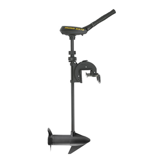
FEATURES Battery Meter Tilt/Extend Tiller Quick Release Depth Collar Steering Tension Knob Tilt Lock Button Transom Clamp Screws Lifetime Warranty Flexible Composite Shaft Power Propeller Cool Quiet Power Motor NOTICE: Specifications subject to change without notice. This diagram is for reference only and may differ from your actual motor. -
Page 8: Installation
INSTALLATION MOTOR INSTALLATION Find a transom area of the boat that is free from obstructions. Transom Mounting Open the Transon Clamp Screws on the bracket Bracket enough so that it will fit over the top of the boat transom. Place the Mounting Bracket over the top of the boat transom so that the bracket is resting on top of the transom. -
Page 9: Battery & Wiring Installation
CAUTION These guidelines apply to general rigging to support your Minn Kota motor. Powering multiple motors or additional electrical devices from the same power circuit may impact the recommended conductor gauge and circuit breaker size. If you are using wire longer than that provided with your unit, follow the conductor gauge and circuit breaker sizing table below. -
Page 10: Selecting The Correct Batteries
Review your charger’s manual carefully or consult the manufacturer prior to use to ensure your charger is compatible. Minn Kota recommends using Minn Kota brand chargers to recharge the batteries connected to your Minn Kota trolling motor, as they have been engineered to work with motors that include a bonding wire. -
Page 11: Connecting The Batteries
CONNECTING THE BATTERIES The negative (-) connection must be connected to the negative terminal of the same battery that the trolling motor negative lead connects to. In the diagrams below this battery is labeled “Low Side” Battery. Connecting to any other trolling motor battery will input positive voltage into the “ground”... -
Page 12: Connecting The Batteries In Series
CONNECTING THE BATTERIES IN SERIES CONNECTING THE BATTERIES IN SERIES (IF REQUIRED FOR YOUR MOTOR) 24 Volt Systems Two 12 volt batteries are required. The batteries must be wired in +24 Volts to trolling motor positive (or circuit breaker) series, only as directed in wiring diagram, to provide 24 volts. To trolling motor negative Make sure that the motor is switched off 24 Volt Series Connection... -
Page 13: Motor Wiring Diagram
MOTOR WIRING DIAGRAM TRAXXIS The following Motor Wiring Diagram applies to all Traxxis models that come factory installed with a variable speed switch. Black M- Speed Adjustment Switch Battery Gauge Red B+ Black B- Black Battery 1 Motor Battery 1... -
Page 14: Using & Adjusting The Motor
USING & ADJUSTING THE MOTOR STOWING AND DEPLOYING THE MOTOR WARNING When stowing or deploying the motor, keep fingers clear of all hinge and pivot points and all moving parts. Practice proper ergonomics when stowing and deploying the motor to prevent injury. WARNING Moving the motor creates a variety of pinch points. -
Page 15: To Deploy The Motor When Horizontal
TO DEPLOY THE MOTOR WHEN HORIZONTAL Retighten the Steering Tension Knob and slide the Quick Release Depth Collar down to the top of the Quick Steering Tension Knob for transport. Release Depth Collar Steering Tension Knob Shaft TO DEPLOY THE MOTOR WHEN HORIZONTAL Loosen the Quick Release Depth Collar. -
Page 16: To Stow The Motor When Vertical
TO DEPLOY THE MOTOR WHEN VERTICAL TO STOW THE MOTOR WHEN VERTICAL Firmly grasp the motor shaft. Loosen the Steering Tension Knob and lift up on the motor. Retighten the Steering Tension Knob to retain the Shaft vertical stow position of the motor. Quick Release Slide the Quick Release Depth Collar down to the top... -
Page 17: Additional Adjustments
ADJUSTING THE DEPTH OF THE MOTOR ADDITIONAL ADJUSTMENTS Adjusting the Depth of the Motor When setting the depth be sure the top of the motor is submerged at least 12” to avoid churning or agitation of surface water. The propeller must be completely submerged. Firmly grasp the motor shaft and hold it steady. -
Page 18: Adjusting The Steering
WARNING Handle Controls: Off/On, Steering, and Forward/Reverse The Traxxis is not intended to be a primary propulsion motor. Heavy use of the motor can cause elevated motor temperatures, which can be increased by an excessively hot WARNING operating environment. Use care when handling the Control Head to avoid burns or injuries from excessive heat. -
Page 19: Controlling Speed & Direction With The Tiller
Tilt/Extend Tiller to turn the prop off. Be alert for unexpected boat movement when operating the Traxxis. The boat may encounter sharp turns and jolts if the steering is changed sharply or if broad changes in speed are made while operating. -
Page 20: Push-To-Test Battery Meter
ADJUSTING THE STEERING PUSH-TO-TEST BATTERY METER This motor is equipped with a “push-to-test” battery meter. The LED light provides an accurate display of the remaining charge in Push-to-Test the battery. It is only accurate when the motor is off. Battery Meter The meter reads as: •... -
Page 21: Service & Maintenance
SERVICE & MAINTENANCE PROPELLER REPLACEMENT TOOLS AND RESOURCES REQUIRED • 1/2” Open End Wrench • Flat Blade Screwdriver INSTALLATION Disconnect the motor from all sources of power prior to changing the propeller. Drive Pin Armature Shaft Hold the propeller and loosen the Prop Nut with a pliers or a wrench. -
Page 22: General Maintenance
GENERAL MAINTENANCE GENERAL MAINTENANCE • After use, the entire motor should be rinsed with freshwater. This series of motors is not equipped for saltwater exposure. • The composite shaft requires periodic cleaning and lubrication for proper retraction and deployment. A coating of an aqueous based silicone spray will improve operation. -
Page 23: For Further Troubleshooting And Repair
Authorized Service Centers Minn Kota has over 800 authorized service providers in the United States and Canada where you can purchase parts or get your products repaired. Please visit our Authorized Service Center page on our website to locate a service provider in your area. -
Page 24: Compliance Statements
Minn Kota motors are not subject to the disposal regulations EAG-VO (electric devices directive) that implements the WEEE directive. Nevertheless never dispose of your Minn Kota motor in a garbage bin but at the proper place of collection of your local town council. - Page 25 COMPLIANCE STATEMENTS NOTICE: This equipment has been tested and found to comply with the limits for a Class B digital device, pursuant to part 15 of the FCC Rules. These limits are designed to provide reasonable protection against harmful interference in a residential installation.
-
Page 26: Parts Diagram & Parts List
TRAXXIS 55 - 55 LBS THRUST - 12 VOLT - 36” & 42” SHAFT This page provides Minn Kota® WEEE compliance disassembly instructions. For more information about where you should dispose of your waste equipment for recycling and recovery and/or your European Union member state requirements, please contact your dealer or distributor from which your product was purchased. - Page 27 PARTS DIAGRAM & PARTS LIST Traxxis 55 Parts List Assembly Part # Description Quantity Item Part # Description Quantity 2097074 12V MOTOR 42” FW 2062905 STRAIN RELIEF 2888460 SEAL AND O-RING KIT 2303412 SCREW, #6-20 X 5/8 SS 2888411 POTENTIOMETER REPLACEMENT KIT 2063410 SCREW, #10-32 X 3/4”...
- Page 28 Stop buying new batteries and start taking care of the ones you’ve got. Many chargers can actually damage your battery over time – creating shorter run times and shorter overall life. Digitally controlled Minn Kota chargers are designed to provide the fastest charge that protect and extend battery life.
Need help?
Do you have a question about the TRAXXIS and is the answer not in the manual?
Questions and answers