Advertisement
Quick Links
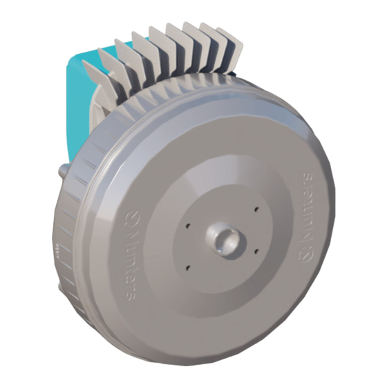
"MD2"
Munters Drive* G2
Motor & Controller
Instruction Manual
Replacement Kit for
ATS74 and CX74 Fans
*Patents Pending
Front View
Rear View
"MD2" Munters Drive G2
Motor and Controller Replacement Kit
Models: MD2-ATS7443-HO • MD2-ATS7443-HE •
MD2-CX7443-HO
© Munters Corporation, December 2023
1
QM1504r0
Advertisement

Related Manuals for Munters MD2


Summary of Contents for Munters MD2
- Page 1 Munters Drive* G2 Motor & Controller Instruction Manual Replacement Kit for ATS74 and CX74 Fans *Patents Pending Front View Rear View “MD2” Munters Drive G2 Motor and Controller Replacement Kit Models: MD2-ATS7443-HO • MD2-ATS7443-HE • MD2-CX7443-HO © Munters Corporation, December 2023 QM1504r0...
- Page 2 With the proper installation and maintenance it will provide many years of service. Please Note: To achieve maximum performance and insure long life from your Munters product it is essential that it be installed and maintained properly. Please read all instructions carefully before beginning installation. Warranty: For Warranty claims information see the “Warranty Claims and Return Policy”...
- Page 3 Index Chapters Page 1. Unpacking the Equipment Parts List 2. Installation Instructions MD2 Replacement for Atlas 74 Fan MD2 Replacement for CX74 Fan 3. Electrical Wiring Atlas 74 GA500 Drive Wiring CX74 Drive Wiring 4. Troubleshooting © Munters Corporation, December 2023...
-
Page 4: Unpacking The Equipment
M8-1.25 x 20mm, HX, Bolt, ZP KW4906 M8 EXT Star Lock Washer, BLK OX If you are Installing this MD2 kit on an Atlas 74 Exhaust Fan, proceed to Page 5 , Step 1. Page 15 , Step 13. If you are installing this MD2 Kit on a CX74 Circulation Fan, proceed to See Figures below. -
Page 5: Installation Instructions
Installation Instructions 2.1 MD2 Replacement for Atlas74 Fan Step 1 Disconnect power from fan before continuing. Remove the shutter from the back of the fan and set safely aside to be reinstalled later. See Figure 1. Figure 1 Step 2 For the Atlas 74 Fan it will be necessary to work from the front of the fan as well as the back of the fan, so remove the outlet guard and bottom cone section of the cone for easy access. - Page 6 Step 3 Loosen the (4) captured screws in the Munters Drive Box cover to access the drive wiring. Make a note of or take a photo of the wiring. Disconnect 3 phase power and the control wires from the drive and from the box.
- Page 7 A gear puller or prop puller may need to be used. See Figure 4. Remove Key from Prop Adapter and keep with prop to be reused later. Set Screw Figure 4 © Munters Corporation, December 2023 QM1504r0...
- Page 8 Remove the (4) Bolts and Star Washers holding the Prop Adapter to the Motor. Save the Prop Adapter for reuse later, but discard the existing bolts and washers. See Figure 5. Star Washers Bolts Prop Adapter Figure 5 QM1504r0 © Munters Corporation, December 2023...
- Page 9 Motor/Drive. See Figure 6. If you were instructed by Munters office to send the old Motor/Drive back to the office, repack it in the box that new Motor/Drive came in to send back. Motor/Drive Assembly...
- Page 10 Carefully lift Motor/Drive into place and secure in place using (4) Bolts [A] and Star Washers [B]. Tighten Bolts to 60 in-lbs. [6.8 Nm] of torque. See Figure 7. Motor/Drive Assembly Star Washer [B] Bolt [A] Figure 7 QM1504r0 © Munters Corporation, December 2023...
- Page 11 Attach the Prop Adapter removed in Step 5 to new Motor/Drive using (4) new Bolts [A] and Star Washers [B]. Tighten Bolts to 60 in-lbs. [6.8 Nm] of torque. See Figure 8. Washers [B] Bolts [A] Prop Adapter Figure 8 © Munters Corporation, December 2023 QM1504r0...
- Page 12 Step 9 Reinstall propeller onto the reinstalled Prop Adapter, replacing the key removed in Step 5. Tighten the Set Screw to 80 in-lbs. [9.0 Nm] of torque. See Figure 9. Set Screw Figure 9 QM1504r0 © Munters Corporation, December 2023...
- Page 13 Installation Instructions Step 10 Loosen the (4) captured screws in the Munters Drive Box cover to access the drive terminals. Reconnect the 3 phase power and the control wires per the note or photo taken in Step 3. See Figure 10.
- Page 14 Reinstall the shutter in the back of the fan and secure in place with the shutter clips. See Figure 12. Reconnect the power to the fan and make sure the fan operates properly. Figure 12 QM1504r0 © Munters Corporation, December 2023...
- Page 15 Chapter 2 Installation Instructions 2.2 MD2 Replacement for CX74 Fan Step 13 Disconnect power from fan before continuing. Remove the front and rear guards from the fan and set safely aside to be reinstalled later. See Figure 13. Figure 13 ©...
- Page 16 Step 14 Loosen the (4) captured screws in the Munters Drive Box cover to access the drive wiring. Make a note of or taking a photo of the wiring. Disconnect 3 phase power and the control wires from the drive from the and from the box.
- Page 17 A gear puller or prop puller may need to be used. See Figure 15. Remove Key from Prop Adapter and keep with prop to be reused later. Set Screw Figure 15 © Munters Corporation, December 2023 QM1504r0...
- Page 18 Remove the (4) Bolts and Star Washers holding the Prop Adapter to the Motor. Save the Prop Adapter for reuse later, but discard the existing bolts and washers. See Figure 16. Prop Adapter Bolts Star Washers Figure 16 QM1504r0 © Munters Corporation, December 2023...
- Page 19 Motor/Drive. See Figure 17. If you were instructed by Munters office to send the old Motor/Drive back to the office, repack it in the box that new Motor/Drive came in to send back. Bolts...
- Page 20 Carefully lift Motor/Drive into place and secure in place using (4) Bolts [A] and Star Washers [B]. Tighten Bolts to 60 in-lbs. [6.8 Nm] of torque. See Figure 18. Star Washer [B] Bolt [A] Mounting Bracket Motor/Drive Assembly Figure 18 QM1504r0 © Munters Corporation, December 2023...
- Page 21 Attach the Prop Adapter removed in Step 16 to new Motor/Drive using (4) new Bolts [A] and Star Washers [B]. Tighten Bolts to 60 in-lbs. [6.8 Nm] of torque. See Figure 19. Prop Adapter Bolts [A] Washers [B] Figure 19 © Munters Corporation, December 2023 QM1504r0...
- Page 22 Step 20 Reinstall propeller onto the reinstalled Prop Adapter, replacing the key removed in Step 5. Tighten the Set Screw to 80 in-lbs. [9.0 Nm] of torque. See Figure 20. Set Screw Figure 20 QM1504r0 © Munters Corporation, December 2023...
-
Page 23: Chapter 3, Page 27, Cx74 Wiring Section For Wiring Options. If The Guards Were Removed In Step 13, Reinstall Them At This Time
Installation Instructions Step 21 Loosen the (4) captured screws in the Munters Drive Box cover to access the drive terminals. Reconnect the 3 phase power and the control wires per the note or photo taken in Step 3. See Figure 21. -
Page 24: Electrical Wiring
Three Phase Power connection: Run the 3 phase power cable through watertight fitting into the Munters Drive box and connect to the terminals "R/L1, S/L2, T/L3" and Ground in the box. See Figure 22. - Page 25 Then connect a wire from ‘S1’ terminal to the output side of the ‘ON’ relay and then connect a wire from the ‘S7’ terminal to the ouput side of the ‘LOW’ relay. See Figure 25. Do not remove the Factory Installed Jumper. ‘LOW’ Relay ‘ON’ Relay Figure 25 © Munters Corporation, December 2023 QM1504r0...
- Page 26 ‘S1’ terminal. Then connect wires from the 10-0V output in the control to the 'A1' and 'AC' terminals in the Munters Drive Box. The '+' output in the control shoud go to 'A1' and the ' - ' output should go to 'AC'.
- Page 27 3.2 CX74 Drive Wiring Determining Drive type for wiring To access the Drive, loosen the (4) screws in the cover of the Munters Drive box to access the terminals inside to connect power and other cables. If your drive looks like...
- Page 28 Chapter 3 Electrical Wiring Three Phase Power connection - V1000: Run the 3 phase power cable through watertight fitting into the Munters Drive box and connect to the terminals "R/L1, S/L2, T/L3" and Ground in the box. See Figure 30.
- Page 29 Then connect a wire from ‘S1’ terminal to the output side of the 'ON' relay and then connect a wire from the ‘S7’ terminal to the ouput side of the ‘LOW’ relay. See Figure 33. Do not remove the Factory Installed Jumper. ‘LOW’ Relay ‘ON’ Relay Figure 33 © Munters Corporation, December 2023 QM1504r0...
- Page 30 ‘S1’ terminal. Then connect wires from the 10-0V output in the control to the 'A1' and 'AC' terminals in the Munters Drive Box. The '+' output in the control shoud go to 'A1' and the ' - ' output should go to 'AC'.
- Page 31 Do not remove the Factory Installed Jumbers. Figure 36 Three Phase Power connection - GA500: Run the 3 phase power cable through watertight fitting into the Munters Drive box and connect to the terminals "R/L1, S/L2, T/L3" and Ground in the box. See Figure 37.
- Page 32 To operate the fan On/Off with a control, wire an 'ON' command from the 'SN' terminal to the input relay in the control and from the output of the control relay to the 'S1' terminal. See Figure 39. Do not remove the Factory Installed Jumpers. Figure 39 QM1504r0 © Munters Corporation, December 2023...
- Page 33 ‘S1’ terminal. Then connect wires from the 10-0V output in the control to the 'A1' and 'AC' terminals in the Munters Drive Box. The '+' output in the control shoud go to 'A1' and the ' - ' output should go to 'AC'.
- Page 34 Figure 42 Alarm Connections - GA500 The Munters Drive uses a Normally Closed circuit for alarm connections. To connect a control to the Normally Closed output make appropriate connecions from the control to ‘MB’ and ‘MC’ terminals. See Figure 43.
-
Page 35: Troubleshooting
3. Verify Prop turns freely an 'On' command is present. a. If not contact Munters Product Support b. If it turns freely go to next step 4. Turn AC power back on to fan a. - Page 36 Munters Drive replacement kit is developed and produced by Munters Corporation, Lansing, Michigan U.S.A. 1-800-227-2376 Munters Europe AB, Isafjordsgatan 1, P.O. Box 1150, SE-164 26 Kista, Sweden. Phone +46 08 626 63 00, Fax +46 8 754 56 66. Munters Corporation 2691 Ena Drive Lansing, MI 48917 U.S.A. Phone +1 800-227-2376, Fax +1 517-676-7078 www.munters.us...
Need help?
Do you have a question about the MD2 and is the answer not in the manual?
Questions and answers