Advertisement
Quick Links
Munters Drive* G2
Controller
Replacement Kit for
Instruction Manual
ATS74 and CX74 Fans
*Patents Pending
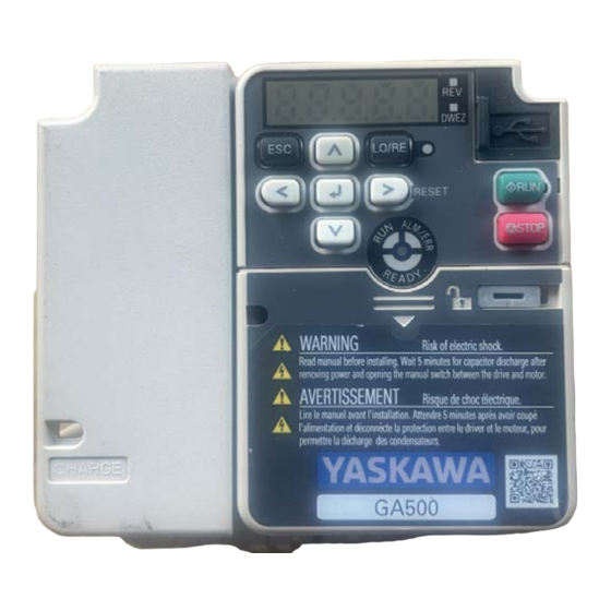
GA500 Controller for ATlas74/CX74
V1000 Controller for CX74 only
Munters Drive G2
Controller Replacement Kit for ATS74/CX74
Models: FC4465-ATS7443HO • FC4465-ATS7443HE •
FC2460-CX7443HO
© Munters Corporation, December 2023
1
QM1505r0
Advertisement

Related Manuals for Munters G2


Summary of Contents for Munters G2
- Page 1 Replacement Kit for Instruction Manual ATS74 and CX74 Fans *Patents Pending GA500 Controller for ATlas74/CX74 V1000 Controller for CX74 only Munters Drive G2 Controller Replacement Kit for ATS74/CX74 Models: FC4465-ATS7443HO • FC4465-ATS7443HE • FC2460-CX7443HO © Munters Corporation, December 2023 QM1505r0...
- Page 2 With the proper installation and maintenance it will provide many years of service. Please Note: To achieve maximum performance and insure long life from your Munters product it is essential that it be installed and maintained properly. Please read all instructions carefully before beginning installation. Warranty: For Warranty claims information see the “Warranty Claims and Return Policy”...
-
Page 3: Table Of Contents
Page 1. Unpacking the Equipment Parts List 2. Installation Instructions MD2 Replacement for Atlas 74 Fan MD2 Replacement for CX74 Fan 3. Electrical Wiring Atlas 74 GA500 Drive Wiring CX74 Drive Wiring 4. Troubleshooting © Munters Corporation, December 2023 QM1505r0... -
Page 4: Unpacking The Equipment
Any shipping damage is the customer’s responsibility and should be reported immediately to your freight carrier. Each Munters Drive G2 Controller Replacement Kit Includes: 1 – Munters Drive G2 Motor/Controller Assembly 1 – Hardware Package As Follows: HP1346 –... -
Page 5: Installation Instructions
2.1 Controller Replacement for Atlas74 Fan Step 1 Disconnect power from fan before continuing. Remove the shutter from the back of the fan and set safely aside to be reinstalled later. See Figure 1. Figure 1 © Munters Corporation, December 2023 QM1505r0... - Page 6 Step 2 Loosen the (4) captured screws in the Munters Drive Box cover to access the drive wiring. Make a note of or take a photo of the wiring. Disconnect 3 phase power and the control wires from the drive and from the box.
- Page 7 Remove the blue Controller Enclosure from the heat sink by removing the (4) Bolts holding it in place. Save the bolts to reinstall the enclosure later. See Figure 3. Bolt Controller Enclosure Figure 3 © Munters Corporation, December 2023 QM1505r0...
- Page 8 Chapter 2 Installation Instructions Step 4 Remove the (4) Bolts holding the Controller to the heat sink. Discard the existing bolts. See Figure 4. Bolts, Discard Controller Figure 4 QM1505r0 © Munters Corporation, December 2023...
- Page 9 Chapter 2 Installation Instructions Step 5 Attach the new Munters Drive Controller to the heat sink where the old one was and secure it in place with (4) Bolts [A]. See Figure 5. Bolt [A] New Controller Figure 5 © Munters Corporation, December 2023...
- Page 10 Chapter 2 Installation Instructions Step 6 Replace the Controller Enclosure and secure it in place using the (4) Bolts that were removed in Step 3. See Figure 6. Existing Bolt Controller Enclosure Figure 6 QM1505r0 © Munters Corporation, December 2023...
- Page 11 Enclosure Cover and secure with the (4) Captured Screws. See Figure 7. If needed refer to Chapter 3, Page 20, Atlas 74 wiring section for wiring options. Munters Drive Box cover Captured Cover Screw Drive Control Wiring Terminals Figure 7 © Munters Corporation, December 2023 QM1505r0...
- Page 12 Reinstall the shutter in the back of the fan and secure in place with the shutter clips. See Figure 8. Reconnect the power to the fan and make sure the fan operates properly. Figure 8 QM1505r0 © Munters Corporation, December 2023...
- Page 13 2.2 Controller Replacement for CX74 Fan Step 9 Disconnect power from fan before continuing. Remove the rear guard from the fan and set safely aside to be reinstalled later. See Figure 9. Figure 9 © Munters Corporation, December 2023 QM1505r0...
- Page 14 Step 10 Loosen the (4) captured screws in the Munters Drive Box cover to access the drive wiring. Make a note of or taking a photo of the wiring. Disconnect 3 phase power and the control wires from the drive from the and from the box.
- Page 15 Remove the blue Controller Enclosure from the heat sink by removing the (4) Bolts holding it in place. Save the bolts to reinstall the enclosure later. See Figure 11. Bolt Controller Enclosure Figure 11 © Munters Corporation, December 2023 QM1505r0...
- Page 16 Chapter 2 Installation Instructions Step 12 Remove the (4) Bolts holding the Controller to the heat sink. Discard the existing bolts. See Figure 12. Prop Adapter Bolts Figure 12 QM1505r0 © Munters Corporation, December 2023...
- Page 17 Chapter 2 Installation Instructions Step 13 Attach the new Munters Drive Controller to the heat sink where the old one was and secure it in place with (4) Bolts [A]. See Figure 13. New Controller Bolts [A] Figure 13 © Munters Corporation, December 2023...
- Page 18 Chapter 2 Installation Instructions Step 14 Replace the Controller Enclosure and secure it in place using the (4) Bolts that were removed in Step 3. See Figure 14. Controller Enclosure Existing Bolt Figure 14 QM1505r0 © Munters Corporation, December 2023...
- Page 19 If needed refer to Chapter 3, Page 23, CX74 wiring section for wiring options. If the guards were removed in Step 9, reinstall them at this time. Captured Cover Screw Munters Drive Box cover Wiring Terminals Figure 15 © Munters Corporation, December 2023 QM1505r0...
-
Page 20: Electrical Wiring
Three Phase Power connection: Run the 3 phase power cable through watertight fitting into the Munters Drive box and connect to the terminals "R/L1, S/L2, T/L3" and Ground in the box. See Figure 22. - Page 21 Then connect a wire from ‘S1’ terminal to the output side of the ‘ON’ relay and then connect a wire from the ‘S7’ terminal to the ouput side of the ‘LOW’ relay. See Figure 25. Do not remove the Factory Installed Jumper. ‘LOW’ Relay ‘ON’ Relay Figure 25 © Munters Corporation, December 2023 QM1505r0...
- Page 22 ‘S1’ terminal. Then connect wires from the 10-0V output in the control to the 'A1' and 'AC' terminals in the Munters Drive Box. The '+' output in the control shoud go to 'A1' and the ' - ' output should go to 'AC'.
-
Page 23: Cx74 Drive Wiring
3.2 CX74 Drive Wiring Determining Drive type for wiring To access the Drive, loosen the (4) screws in the cover of the Munters Drive box to access the terminals inside to connect power and other cables. If your drive looks like... - Page 24 Chapter 3 Electrical Wiring Three Phase Power connection - V1000: Run the 3 phase power cable through watertight fitting into the Munters Drive box and connect to the terminals "R/L1, S/L2, T/L3" and Ground in the box. See Figure 30.
- Page 25 Then connect a wire from ‘S1’ terminal to the output side of the 'ON' relay and then connect a wire from the ‘S7’ terminal to the ouput side of the ‘LOW’ relay. See Figure 33. Do not remove the Factory Installed Jumper. ‘LOW’ Relay ‘ON’ Relay Figure 33 © Munters Corporation, December 2023 QM1505r0...
- Page 26 ‘S1’ terminal. Then connect wires from the 10-0V output in the control to the 'A1' and 'AC' terminals in the Munters Drive Box. The '+' output in the control shoud go to 'A1' and the ' - ' output should go to 'AC'.
- Page 27 Do not remove the Factory Installed Jumbers. Figure 36 Three Phase Power connection - GA500: Run the 3 phase power cable through watertight fitting into the Munters Drive box and connect to the terminals "R/L1, S/L2, T/L3" and Ground in the box. See Figure 37.
- Page 28 To operate the fan On/Off with a control, wire an 'ON' command from the 'SN' terminal to the input relay in the control and from the output of the control relay to the 'S1' terminal. See Figure 39. Do not remove the Factory Installed Jumpers. Figure 39 QM1505r0 © Munters Corporation, December 2023...
- Page 29 ‘S1’ terminal. Then connect wires from the 10-0V output in the control to the 'A1' and 'AC' terminals in the Munters Drive Box. The '+' output in the control shoud go to 'A1' and the ' - ' output should go to 'AC'.
- Page 30 Figure 42 Alarm Connections - GA500 The Munters Drive uses a Normally Closed circuit for alarm connections. To connect a control to the Normally Closed output make appropriate connecions from the control to ‘MB’ and ‘MC’ terminals. See Figure 43.
-
Page 31: Troubleshooting
3. Verify Prop turns freely an 'On' command is present. a. If not contact Munters Product Support b. If it turns freely go to next step 4. Turn AC power back on to fan a. - Page 32 Munters Drive Controller replacement kit is developed and produced by Munters Corporation, Lansing, Michigan U.S.A. 1-800-227-2376 Munters Europe AB, Isafjordsgatan 1, P.O. Box 1150, SE-164 26 Kista, Sweden. Phone +46 08 626 63 00, Fax +46 8 754 56 66.
Need help?
Do you have a question about the G2 and is the answer not in the manual?
Questions and answers