Summary of Contents for Munters Green RTU
- Page 1 RTU RX Module User Manual Program Green RTU RX Module Programming Communication Device Ag/MIS/UmEn-2764-05/20 Rev 1.4 P/N: 116811...
- Page 2 Green RTU RX Module Programming User Manual Revision: N.1.4 of 06.2024 Product Software: N/A This manual for use and maintenance is an integral part of the apparatus together with the attached technical documentation. This document is destined for the user of the apparatus: it may not be reproduced in whole or in part, committed to computer memory as a file or delivered to third parties without the prior authorization of the assembler of the system.
-
Page 3: Table Of Contents
Step 6: Setting the Receiver Modules Frequency Channel ....2.5.7 Step 7: Programming the Receiver Module with the Various Settings11 How to Read the Receiver Module ................ 11 Disconnecting the Receiver Module From HHP ..........12 ......................... WARRANTY © Munters AB, 2020... -
Page 4: Introduction
Munters Controllers. 1.3 Notes Date of release: May 2020 Munters cannot guarantee to inform users about the changes or to distribute new manuals to them. NOTE All rights reserved. No part of this manual may be reproduced in any manner whatsoever without the expressed written permission of Munters. -
Page 5: Installing The Hand Held Programmer's Battery
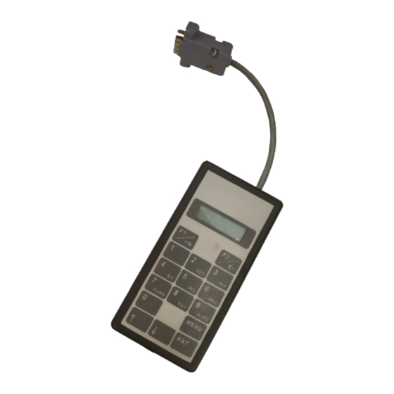
NOTE Referred to as the HHP to the Receiver Module Open the battery housing on the receiver module by removing the rubber plug • from the receiver modules battery compartment (Do not use any sharp instruments to achieve this). © Munters AB, 2020... - Page 6 Yellow, Blue and Green wires are terminated in a plug. The interfacing harness will also be equipped with a Red reset button mounted on the cover of the DB9 connector of the harness cable. © Munters AB, 2020...
-
Page 7: Resetting The Receiver Module
Use the ▲ and ▼ keys on the programmer’s keypad to navigate between the • different functions. The ▼ key moves between menus in ascending order (i.e. from menu 1 to menu 10). The ▲ key moves between menus in descending order (i.e. from menu 10 to menu 1) © Munters AB, 2020... -
Page 8: Understanding The Settings Fields Screen On The Hhp
NOTE Avoid setting the Receiver modules first output address in a region that will cause the second, third or fourth output to overlap the output values 32 and 33, 64 and 65, or 96 and 97. © Munters AB, 2020... -
Page 9: Step 2: Setting The Number Of Outputs Required On The Receiver Module
ODULES XTRA NOTE This feature is not supported by GREEN RTU receiver modules. The Extra Sys(tem) ID pairs the Receiver module with a transmitter device set with the same Extra Sys ID. It works in the same manner as the System ID as explained under Step 3 above. -
Page 10: Step 5: Setting The Receiver Modules Unit Type
NOTE If the software version POPTX XX is available on the systems radio transmitter interface card or if the RX Module/s being used are GREEN RTU, the module should be set to the NEW type. If the software version REMTX XX is available on the systems radio transmitter interface card, the module should be set to the OLD type. -
Page 11: Step 7: Programming The Receiver Module With The Various Settings11
The Green LED will flash on for a further few seconds and extinguish where after the setting relevant to this Receiver module should then appear on the screen of the HHP (as per the image below). This may take a few seconds to update. © Munters AB, 2020... -
Page 12: Disconnecting The Receiver Module From Hhp
If data that pertains to one or more of the outputs has been received by the • module, the output/s will be activated or deactivated dependent on the status requested. At this time during the 5 minute period the green LED will also flash briefly. © Munters AB, 2020... -
Page 13: Warranty
Munters plant was required: if this is not done, the user is fully responsible for the damage which they could suffer. - Page 14 Dismantling and assembly must be performed by qualified technicians and according to the manufacturer’s instructions. The use of non-original spare parts or incorrect assembly exonerates the manufacturer from all liability. Requests for technical assistance and spare parts can be made directly to the nearest Munters office. © Munters AB, 2020...


Need help?
Do you have a question about the Green RTU and is the answer not in the manual?
Questions and answers