
Related Manuals for Munters SMART-8C


Summary of Contents for Munters SMART-8C
- Page 1 SMART- 8C/3MD Manual for use and maintenance SMART-8C/3MD Climate Controller Ag/MIS/UmGB-2375-07/16 rev 1.2 P/N: 110591...
- Page 2 Munters reserves the right to effect modifications to the apparatus in accordance with technical and legal developments. © Munters AB, 2016...
-
Page 3: Table Of Contents
Introduction ....................5 Notes ......................5 Precautions ........................6 Grounding ....................6 Checking the battery level ................6 Introduction to the SMART-8C/3MD ................7 Features ......................7 Theory of operation ..................7 3.2.1 Mode ..........................7 3.2.2 Fan operation ........................ 7 3.2.3 Curtains .......................... - Page 4 Electrical grounding for controllers ................24 Ground rods ....................24 Ground wire ....................25 Ground clamps .................... 25 What should be grounded? ................25 Technical specifications ..................... 26 Troubleshooting ......................27 Appendix 1: Features parameters ................28 Warranty ........................31 © Munters AB, 2016...
-
Page 5: Introduction
The information contained herein has been prepared by qualified experts within Munters. While we believe the information is accurate and complete, we make no warranty or representation for any particular purposes. The information is offered in good faith and with the understanding that any use of the units or accessories in breach of the directions and warnings in this document is at the sole discretion and risk of the user. -
Page 6: Precautions
2.2 Checking the battery level Check the battery once a year. The output must be 2.7 volts (minimum). Authorized personnel only must replace the battery if the output is below the minimum required level or every five years. © Munters AB, 2016... -
Page 7: Introduction To The Smart-8C/3Md
SMART-8C/3MD gives you control over the temperature and humidity in buildings using intelligent, user-friendly climate control software. The primary function of SMART-8C/3MD is to control the fans; the secondary function is to control curtains. Ventilation also includes fogging and soaking options. -
Page 8: Curtains
Relay controlled fans: There are three relay controlled fans that provide additional • ventilation. These fans turn on when the Munters Drive fans turn on. 3.2.3 Curtains The controllers open and close curtains according to temperature readings. In the presence of high wind speeds, the curtains can be set to a minimum position. -
Page 9: Menu Structure
LCD test 3.6 General features If a screen other than the main screen is displayed for five consecutive minutes, the system • returns to the main screen display automatically (in menus only, not including Hot Keys). © Munters AB, 2016... -
Page 10: Leds
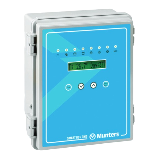
If the system displays a Hot Key screen and alarms arise, both the Hot Key screen and the alarm are displayed alternately every three seconds. If more than one alarm is activated, the Hot Key screen displays the different alarms alternately. 3.7 LEDs The following illustrations detail the SMART-8C/3MD LEDs Fogger Soaker Curtain Open... -
Page 11: Using The Smart-8C/3Md
4 Using the SMART-8C/3MD The following sections detail: Initial Setup, page 11 • Sensor Configuration, page 12 • Testing sensors and relays, page 13 • Cooling, page 14 • 4.1 Initial Setup The following sections detail the initial steps to be taken after installing a unit. -
Page 12: Sensor Configuration
The alarm message remains on the screen. Table 2 lists the alarm messages. View the alarms on the main screen. The main screen displays the alarms and the main screen alternately. SMART-8C/3MD navigates between the alarms automatically. -
Page 13: Configuring Digital Input Sensors
4.2.2 Configuring digital input sensors This section details how to install the digital inputs. SMART-8C/3MD can support a water counter and a wind speed reader. Each digital input is optional and independently installed. NOTE Only perform the steps required for your particular installation. -
Page 14: Cooling
The following sections detail how to configure the cooling methods. • Munters Drive fans • Foggers and soakers • Configuring the curtain 4.4.1 Munters Drive fans The following sections detail how to configure the Munters Drive fans. Munters Drive background • Configuring the Munters Drive fans •... -
Page 15: Foggers And Soakers
4.4.2 Foggers and soakers The following section details how to configure the foggers and soakers. These work in conjunction with the Munters Drive Fans. Soakers work with Munters Drive 1, foggers work with Munters Drive 2. Fogger and soaker background •... - Page 16 Figure 3: Graph demonstrating Zone 1 ventilation and soaking NOTE When soakers operate, Fan1 is disabled. The fans go from 0 to 100% based on the Munters Drive Temp Diff and Temp Band • parameters (Munters Drive fans setup). Soakers begin operating based on the Temp Diff On parameter (Fogger and soaker setup) •...
- Page 17 (for example 13:15 to 13:15) disables the fogger and soaker. 5. Press Select. 6. Scroll to Fan 2 and Fan 3 and press Prog. 7. Repeat step 4. 8. Press Prog. 9. Press Select. © Munters AB, 2016...
-
Page 18: Configuring The Curtains
7. Scroll to System and press Prog. 8. Scroll to High Wind Speed and press Prog. 9. Define the wind speed above which all devices turn off and curtain goes to minimum position. 10. Press Prog. © Munters AB, 2016... -
Page 19: Installation
Multi wire supply! Up to nine independent mains input may be present in the SMART- WARNING! 8C/3MD Controller. Put all appropriate circuit breakers in the OFF position before servicing. 5.2 SMART-8C/3MD wiring The following drawings detail the SMART-8C/3MD wiring. Before wiring the unit, disconnect the power! WARNING! Figure 6: Board Layout •... - Page 20 Figure 6: Board Layout © Munters AB, 2016...
- Page 21 Figure 7: Wiring Diagram of Low Voltage Section © Munters AB, 2016...
- Page 22 Figure 8: Wiring Diagram of Main Voltage Section and Protection NOTE The above diagram is an example only and subject to change. © Munters AB, 2016...
-
Page 23: Communication Wiring
5.3 Communication wiring Figure 9: SMART-8C/3MD Communication RS-232 Wiring Diagram © Munters AB, 2016... -
Page 24: Electrical Grounding For Controllers
Electrical equipment can be destroyed or slowly damaged by voltage spikes, lightning hits, etc. Proper electrical grounding in combination with the SMART-8C/3MD internal protections is essential to protect the system, reduce the risk of damage and prolong its lifetime. Correct selection and installation of equipment will protect your system and reduce the risk of human injury. -
Page 25: Ground Wire
Electric circuits should be wired with a 3-wire conductor consisting of hot, neutral and grounding wires. The grounding wire should be attached cleanly and securely to devices or systems to be grounded. The other end of the grounding wire should be attached to the ground bus on the main panel. © Munters AB, 2016... -
Page 26: Technical Specifications
5 mA @ 5 volts, dry contact 2 inputs (wind speed, water measurement) Operating Temperature Range 0° to +50° C (32° to 125° F) Enclosure Water and Dust Tight Fuses Main fuse: 0.100 Amps, 250 Volts Relay Fuse © Munters AB, 2016... -
Page 27: Troubleshooting
LCD or CPU problem Replace LCD or CPU card blinking Sensor disconnected Alarm or Sensor fail or not properly Connect sensor properly connected CAUTION In case of hardware problems, do not open the box. Contact an authorized electrician. © Munters AB, 2016... -
Page 28: Appendix 1: Features Parameters
Minimum Position (%) Time From 08:00 00:00 23:59 Time To 17:00 00:00 23:59 Table 4: Munters Drive Fan Parameters Summary Parameter Name Default Value Increment Value Min Value Max Value Temp Diff -3 ° F -20 ° F 40 ° F Temp Band +3 °... - Page 29 999.0 Curtain Open/Close (seconds) Fan-1/2/3 Min Volt 10.0 Fan-1/2/3 Max Volt 10.0 Table 9: System Menu Summary Parameter Name Default Value Increment Value Possible Value Control Method Temp Temp/THI Temp-3 Out/In Wind Speed 0 to 80 © Munters AB, 2016...
- Page 30 1, 2, 3, 4, 5, 6, 8 hrs., 1 day Time No default 1 minute 00:00 – 23:59 Unit Number 0 - 255 Baud Rate 9600 2400, 4800, 9600, 19200 This section explains the logic used for each cooling device. © Munters AB, 2016...
-
Page 31: Warranty
12 months of the delivery of the defective product. Munters has thirty days from the date of receipt in which to take action, and has the right to examine the product at the customer’s premises or at its own plant (carriage cost to be borne by the customer). - Page 32 The use of non-original spare parts or incorrect assembly exonerates the manufacturer from all liability. Requests for technical assistance and spare parts can be made directly to the nearest Munters office. A full list of contact details can be found on the back page of this manual.
- Page 33 Munters Brasil Industria e Comercio Ltda, Phone +55 41 3317 5050, Canada Munters Corporation Mason, Phone +1 517 676 7070, China Munters Air Treatment Equipment (Beijing) Co. Ltd, Phone +86 10 80 418 000, Denmark Munters A/S, Phone +45 9862 3311, India...
Need help?
Do you have a question about the SMART-8C and is the answer not in the manual?
Questions and answers