
Subscribe to Our Youtube Channel
Related Manuals for Munters Farm Premium


Summary of Contents for Munters Farm Premium
- Page 1 Farm Premium Controllers User Manual Farm Premium, Premium-P, Premium XL, P-XL Climate Controllers for Poultry and Pigs Ag/MIS/UmGB-2224-01/15 Rev. 1.7 P/N: 110476...
- Page 2 Munters reserves the right to effect modifications to the apparatus in accordance with technical and legal developments. © Munters AB, 2015...
-
Page 3: Table Of Contents
Static Pressure ------------------------------------------------------------------------------------------------------------------------------------------------------------- 3.6.1 Disabling the Static Pressure Sensor 3.6.2 Static Pressure Help | Set Definitions 3.6.3 Multi Stage Tunnel Curtains Control Mode ------------------------------------------------------------------------------------------------------------------------------------------------------------- System Parameters --------------------------------------------------------------------------------------------------------------------------------------------------- Ammonia Treatment ------------------------------------------------------------------------------------------------------------------------------------------------ 3.9.1 Ammonia Treatment Help | Set Definitions © Munters AB, 2015... - Page 4 4.13.5 Natural Programming Help | Set Definitions 4.13.6 Natural Program Hot Screen 4.13.7 What Happens When the Controller Transitions? 4.14 Feed Scale Program ------------------------------------------------------------------------------------------------------------------------------------------------ 4.14.1 Feed Scale Help | Set Definitions 4.14.2 Feed Scale Hot Screen MANAGE MENU -------------------------------------------------------------------------------------------------------------------------------------- 66 Inventory ------------------------------------------------------------------------------------------------------------------------------------------------------------------------ © Munters AB, 2015...
- Page 5 6.9.2 Silo Calibration 6.10 Silo / Auger Layout ------------------------------------------------------------------------------------------------------------------------------------------------- HISTORY MENU ---------------------------------------------------------------------------------------------------------------------------------------- 85 Temperature ----------------------------------------------------------------------------------------------------------------------------------------------------------------- Humidity ------------------------------------------------------------------------------------------------------------------------------------------------------------------------- --------------------------------------------------------------------------------------------------------------------------------------------------------------------------------- Water ------------------------------------------------------------------------------------------------------------------------------------------------------------------------------- Feed ---------------------------------------------------------------------------------------------------------------------------------------------------------------------------------- Mortality ------------------------------------------------------------------------------------------------------------------------------------------------------------------------- Heaters ---------------------------------------------------------------------------------------------------------------------------------------------------------------------------- Radiant Heaters --------------------------------------------------------------------------------------------------------------------------------------------------------- Alarms ------------------------------------------------------------------------------------------------------------------------------------------------------------------------------ 7.10 Table of Events ----------------------------------------------------------------------------------------------------------------------------------------------------------- © Munters AB, 2015...
- Page 6 9.12.2 Loading from an SD Card 9.13 Current Sense Relay Calibration ----------------------------------------------------------------------------------------------------------------- 9.14 Wind Direction Calibration ----------------------------------------------------------------------------------------------------------------------------- 9.15 WOD Calibration ------------------------------------------------------------------------------------------------------------------------------------------------- 9.15.1 WOD Calibration Help | Set Definitions 9.16 Ammonia Calibration ----------------------------------------------------------------------------------------------------------------------------------------- INSTALL MENU ---------------------------------------------------------------------------------------------------------------------------------------- 106 © Munters AB, 2015...
- Page 7 --------------------------------------------------------------------------------------------------------------------------------------------------- 10.9 House Dimensions ------------------------------------------------------------------------------------------------------------------------------------------------ 10.10 Communication ------------------------------------------------------------------------------------------------------------------------------------------------------ APPENDIX A: OUTPUT DATA -------------------------------------------------------------------------------------------------------------- 117 APPENDIX B: FARM PREMIUM LAYERS ------------------------------------------------------------------------------------------- 120 12.1 Layers Main Screen --------------------------------------------------------------------------------------------------------------------------------------------- 12.2 Layers Vent and Curtain Levels --------------------------------------------------------------------------------------------------------------------- 12.2.1 Layer Inlet Control 12.2.2 Layer Vent & Curtain (Inlet) levels help | set definitions ........
-
Page 8: Introduction
The information contained herein has been prepared by qualified experts within Munters. While we believe the information is accurate and complete, we make no warranty or representation for any particular purposes. The information is offered in good faith and with the understanding that any use of the units or accessories in breach of the directions and warnings in this document is at the sole discretion and risk of the user. -
Page 9: Introduction To Precision Mode
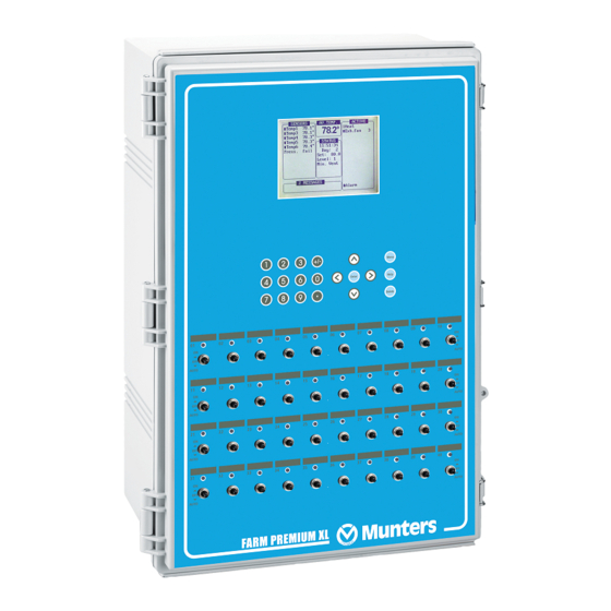
Front Panel, page 9 • Selecting the Mode, page 14 • 2.1 Front Panel Figure 1 shows the Farm Premium-P XL front panel and its elements. All controllers have similar elements. Figure 1: Farm Premium-P XL Front Panel © Munters AB, 2015... -
Page 10: Keypad
Toggle between positive and negative values and mark check boxes 2.1.2 R ELAY WITCHES Figure 2: Standard Relay Switches Figure 2 illustrates a row of standard relay switches. Set each relay to: On: Always on • Off: Always off • © Munters AB, 2015... - Page 11 If two humidity sensors are installed, Hot Screen 2 displays their average. Curve status Curtain, tunnel, vent, and attic opening positions Bird Scale Natural Program Status. Refer to Natural Program Hot Screen, page 61) Light status Analog output status Temperature sensors • Silo status © Munters AB, 2015...
-
Page 12: Main Screen Display
1. Sensors: Displays individual sensor readings. Temperature sensors marked with dark squares form the current average temperature. o Filled square: Indicates the sensor participates in the average calculation. o Empty square: Indicates the sensor does not participate in the average calculation. © Munters AB, 2015... - Page 13 Go to Table 1: Sensor Readings, page 117 to view all the available readings. 5. Messages: Displays important messages/alarms. The title bar displays the number of important messages, and if there are several messages, they each appear in turn. 4 MESSAGES (2) Low Feed At Bin 2 © Munters AB, 2015...
-
Page 14: Selecting The Mode
7. Calibrate temperature, humidity, ventilation, static pressure, feed, water, read/save to plug. 8. Install sensors, devices, communication, etc. 2.2 Selecting the Mode Farm Premium runs in four modes: Broiler, Layer, Breeders, and Pigs. To select the mode: 1. Disconnect the power cable from the power source. -
Page 15: Control Menu
Define: Day: Set the growth day. You can program negative growth days up to -2 for pre- warming. To enter a negative growth day, type the day number followed by the ± key. © Munters AB, 2015... -
Page 16: Temperature Curve Help | Set Definitions
Farm Premiumreminds you. When you press Enter to acknowledge the reminder, the Farm Premium logs it in the Table of Events. Target Temp. Band: The size of the target temperature zone. This "Happy Zone” is between •... -
Page 17: Cycle Heaters | Set Definitions
Cool Down Fast Response (Deg.): Set a limit to the maximum degrees per minute of cooling. • If Average Temperature drops more than this in one minute, the Farm Premium decreases ventilation one level to avoid overshooting. NOTE: Avoid making this parameter too small or the normal temperature variation caused by timer fans reduces the ventilation level. - Page 18 If the temperature continues to drop, heaters operate for longer periods of time, up to the • Maximum On Time (defined in Levels of Ventilation). Farm Premium automatically generates a curve. • In this example: Temperature Curve Heat Off is 78°.
- Page 19 3.1.4 V ARIABLE EATER EFINITIONS The Farm Premium Controller enables configuring up to eight variable heaters. The heater output changes according to the output of a 0 – 10 VDC device. Install at least one analog output card. To configure the variable heaters: 1.
- Page 20 Radiant Ignition Time (sec) VARIABLE HEATER Low Diff Below Heat High Diff Below Heat Define the parameters: • o Low Difference Below Heat: Temperature difference between the Heat Off parameter at which the variable heater begins to function. © Munters AB, 2015...
- Page 21 When the temperature falls below the user-defined point, the heaters begin operating at their • minimum output. After the response time passes, Farm Premium checks the temperature. If it is still below the • defined point, Farm Premium increases the voltage by a certain amount (this amount of the increase cannot be changed).
-
Page 22: Variable Floor Heater | Set Definitions
VARIABLE FLOOR HEATER Low Diff Below Heat Tmp. High Diff Below Heat Tmp. Farm Premium Controllers enable configuring up to two variable floor heaters. The output of the heaters changes as the temperature increases or decreases. Install at least one analog output card. -
Page 23: Introduction To Humidity, Ammonia, And Co2 Treatment
Proportional Heat Refer to the above sections for further information on these modes. 3.2 Introduction to Humidity, Ammonia, and CO2 Treatment Farm Premium provides various options to controlling the humidity, CO2, and ammonia levels. None: No treatment is provided. •... -
Page 24: Humidity Treatment
(outdoor sensor is for information only). When using more than one sensor, Farm Premium begins treatments based on the average. 2. If required, go to Service > Humidity Calibration, and calibrate the sensors (refer to Humidity Calibration, page 95). -
Page 25: Co2 Treatment
2. If required, go to Service > CO2 Calibration and calibrate the sensors (refer to CO2 Sensor, page 96). 3. In Control > CO2 Treatment set the parameters as required. o Day: Growth day. You can set multiple programs for same day (maximum number of programs: 20) © Munters AB, 2015... - Page 26 CO2 Treatment by Heater requires designating at least one temperature sensor as an outside temperature sensor (refer to Temperature Definition, page Error! Bookmark not defined.). NOTE: If the heaters are operating because of the interior temperature only, CO2 Treatment by Heater is disabled. © Munters AB, 2015...
-
Page 27: By Day And By Soft Days Curve
Once you have entered the ventilation levels, use the Min/Max to select the range of levels to apply to your situation. Typically, Farm Premium increases the minimum ventilation level as litter conditions deteriorate and the birds require greater amounts of fresh air. You can also restrict the maximum level to prevent excess airflow on young birds. -
Page 28: Co2 Treatment Help | Set Definitions
The By Weight option enables controlling the minimum air flow depending on the number of birds, their weight and the current outside temperature. When using the Weight option, Farm Premium takes several parameters and calculates the air speed, level of ventilation and cycle time needed to supply the required volume. - Page 29 Warm Temp. – Diff Below Heat Cold Temperature 68.0 Air Change 0.24 Fan Cycle Time (sec, 0 – Manual) Minimum ON Time in Vent Cycle Minimum OFF Time Vent Cycle Air Change by Humidity/CO2 % Air Per Weight Curve Mode © Munters AB, 2015...
- Page 30 Ventilation. During this time, the fans supply the required volume of air at the minimum ventilation level required. Farm Premium adjusts the minimum ON time and OFF time as needed. If the fans cannot supply the required volume at a particular level of ventilation, Farm Premium automatically adjusts the minimum ventilation level.
-
Page 31: Static Pressure
Level: Displays the current, minimum and maximum level of ventilation. • NOTE: If the current level is below the minimum required level, Farm Premium displays an alarm “Below Min Air”. Cycle On/Off: Displays the current, minimum and maximum fan on and off times. - Page 32 Low Static Pressure Alarm: Set alarm for low static pressure. If you disable it by setting zero, • the Farm Premium warns you and enters a record in the Table of Events. High Static Pressure Alarm: Set alarm for high static pressure.
-
Page 33: Multi Stage Tunnel Curtains
Opening the tunnel curtains commences when the target static pressure is reached and the controller signals to the tunnel machine to operate the curtains. Farm Premium opens the first tunnel curtain (as defined in the relays) to the user defined level. If additional ventilation is required, the second tunnel curtain opens. -
Page 34: Static Pressure Help | Set Definitions
System Parameters consolidates all of the HELP | SET menus into one scroll screen. Page System Parameter Temperature Curve Error! Book mark Cycle Heater define Radiant Heater Variable Heater Humidity Treatment CO2 Treatment Static Pressure Ventilation Levels Curtains © Munters AB, 2015... -
Page 35: Ammonia Treatment
Day: Growth day. You can set multiple programs for same day (maximum number of programs: 20) o Start Value: Ammonia value at which to begin treatment. Range: 0 to 100. Default: 2 NOTE: Ammonia levels should not be higher than 30 ppm. © Munters AB, 2015... - Page 36 Exhaust: Designate a specific exhaust fan (press a number key to select the fan). Tunnel: Designate a specific tunnel fan (press a number key to select the fan). None: Disables the treatment. © Munters AB, 2015...
-
Page 37: Device Menu
4 Device Menu The Farm Premium can have many closely spaced levels of ventilation enabling it to find the optimum average airflow for the poultry facility. Many of the levels are at exactly the same temperature setting, so there may be a question as to how the Farm Premium chooses the correct level. -
Page 38: Levels Of Ventilation
0.0. Air Capacity: 300 -Continuous Chill Range: -Cycle -Rotate Tunnel Level: T © Munters AB, 2015... -
Page 39: Levels Of Ventilation Help | Set Definitions
Wind Chill Enable 14.4 Wind Chill Limit RH Effect Define • o Maximum Levels of Ventilation: Set the maximum number of levels. o First Tunnel Level: Set the entry point to tunnel mode. Zero disables this parameter. © Munters AB, 2015... -
Page 40: Wind Chill
4.1.2 W HILL Farm Premium can take into consideration the wind chill factor when making certain calculations related to the temperature. In effect, the wind chill factor acts as the temperature differential. When enabled, Farm Premium determines the “calculated temperature (actual temperature – wind chill temperature) and... -
Page 41: Variable Speed Fan Levels
4. In Device Setting > Vent & Curtain Levels, define the minimum opening percentages. 5. Press Enter. 6. If required, configure each opening to work with a particular temperature sensor. Refer to Temperature Definition, page 114. 7. Set the Help Set parameters as required. © Munters AB, 2015... - Page 42 Operate Until Day: Set the last day for attic operation (broilers only). • Operate From/To Time: Set the time frame for attic operation. • NOTE: If one of the above options is relevant, the Attic is enabled. © Munters AB, 2015...
-
Page 43: Stir Fan Levels
The Stir Fans operate according to the levels you program in this menu, and according to the programs you select in the Stir Fan Program. The fan turns on if any program or level requests ON; all programs and levels must be OFF for the Stir Fan to be off. © Munters AB, 2015... -
Page 44: Stir Fan Program
From Time (hh:mm) 00:00 To Time (hh:mm) 00:00 Stop During Fan Operation PROGRAM B (sensors diff temp) Operate after End of Cycle Delay for Operation Time for Operation From Level To Level 00:00 From Time 00:00 To Time © Munters AB, 2015... - Page 45 Stop During Fan Operation: Select YES run the heaters when the fans are operating. • Variable Stir Fan: Select the stir fan to be used • Min/Max Variable Stir Fan Speed: Enter the minimum and maximum speed (in percentage). • © Munters AB, 2015...
-
Page 46: Cool Pad
• negative differential temperatures. o Note the settings for Day 14. The Farm Premium uses the maximum temperature differential that applies to choose the correct settings. To Humidity: Set maximum humidity allowed before stopping cool pad. You can enter 100%. -
Page 47: Foggers
Difference Between Cool Pads Stage: Farm Premium supports four cooling pad stages. The • controller activates the first stage when the temperature reaches the Tunnel Temperature (Control > Temperature Curve) plus the Tunnel Differentiation (set in the Cool Pad screen). - Page 48 NOTE: Munters recommends keeping this function set at the default setting (No). Difference between Foggers Stage: Farm Premium supports four fogging stages. The • controller activates the first stage when the temperature reaches the Target Temperature (Control >...
-
Page 49: Light
In the example, the brood lights (channel 1) and bright center lights (channel 2) turn on from day 1, while the grow end lights (channel 3) are off. The example shows two channels of light dimmer, Channel 1 at 100% and Channel 2 at 0% (for baby chicks in the brood zone). © Munters AB, 2015... -
Page 50: Light Help | Set Definitions
After the feeding period ends, all lights selected in the Light Parameters screen relight. Signal Before Feed (seconds): Amount of time, before the feeding starts, that all other lights • go off. Signal During Feed (seconds): Amount of time that the selected light remains on after feeding • ends. © Munters AB, 2015... -
Page 51: Water & Feed
4.9 Water & Feed This menu sets the operating conditions for water and feed devices. There are control two methods: Control via Time • Control via Quantity • Water and Feed Help | Set Definitions • © Munters AB, 2015... - Page 52 +/-key. Growth days stay at the defined parameters until the next defined day. From Time/To Time: Set the time period during which water and feeding lines can operate. • Water: Select a check mark to mark water lines to turn on, dot the ones to turn off. • © Munters AB, 2015...
-
Page 53: Control Via Quantity
Quantity: Enable this feature to enable Control by Quantity. • NOTE: If you choose Daily, the Scale function is always enabled. If you choose 2- 6 Days or Week, disabled the Scale function is on non-feeding days. © Munters AB, 2015... -
Page 54: Extra Systems
This selection applies to optional emergency cards. These cards are battery backed, and operate as standard switch and relay cards during normal operation. If an emergency occurs, the cards continue to operate according to their emergency settings. This function requires installing an Emergency card. © Munters AB, 2015... - Page 55 Install | Relay Layout. Your selections will likely be • different from the example above. The Farm Premium does not allow certain selections for the emergency functions. Differential: The difference from target temperature at which the device operates during •...
-
Page 56: Water And Feed Help | Set Definitions
(manual or solenoid according to the mode installed). Farm Premium enables controlling the water cycle times using relays and controlling the water pressure using analog input and output sensors. The two methods are complimentary. A user can use either one alone or both. -
Page 57: Sensor Control
Water Pres. During Flush: Relay Active During Flush: Water Pressure During Flush: Designate the system water pressure when nipple flush is • operative. Relay Active During Flush: Designate which WOD relays remain active during flushing. • © Munters AB, 2015... -
Page 58: Natural Program
Wind and Rain Effect 4.13.1 H ATURAL ENTILATION For Farm Premium to switch to Natural Ventilation: Natural Ventilation works only during the defined growth days and daily schedule. • The temperature inside the chicken house must be within the inside temperature band. -
Page 59: Preliminary Steps
90° total. Winds that come within this area (A) are used for Natural Programing. The controller disregards winds outside of this area (B & C). 4. If required, in Installation > Temperature Definition designate a temperature sensor as an outside sensor. © Munters AB, 2015... - Page 60 • Minimum Wind Speed for Tunnel Temp: When the unit is in Natural Mode, if the temperature • rises above the Tunnel Temperature, Farm Premium switches to Tunnel mode unless the wind speed is above the speed set here. NOTE: The above three parameters require installing and configuring a wind speed sensor.
-
Page 61: Natural Program Hot Screen
Natural Program Status. 4.13.6.1 Ventilation is Not in Natural Mode When Farm Premium is employing Minimum or Tunnel Ventilation, the Hot Screen displays the conditions needed to enter Natural Mode. NOTE: The Between Temp parameters can change based on the wind speed. Refer to Minimum Wind Speed for Tunnel Temp, page 60. -
Page 62: Feed Scale Program
Feed Scale enables mixing different types of feeds from (up to) four different silos. The user fills each bin with the required feed type and sets the mixture rations and quantities in Farm Premium. The augers then distribute the feed as defined. - Page 63 3636 5. Define: o Day: Define the days at which the feed per bird changes. Farm Premium calculates a feed curve based on these days. You can define the days as negative days. Enter the day number and press +/-.
-
Page 64: Feed Scale Hot Screen
The number does not need to be exact. In the following feed runs, Farm Premium will correct the amount entered. o Optimizer: This parameter sets the unit's sensitivity to signal noise (caused by a variety of factors). - Page 65 Define this sensor in Install > Digital Sensor. This screen shows the sensor's current status. If the feed reaches this sensor, an alarm is generated. Alarm: This parameter shows if there are active alarms. View the alarms on the Main Screen. • © Munters AB, 2015...
-
Page 66: Manage Menu
Total Dead Animals Total Culled Total Culled Total Birds Moved 1020 1530 Total Animals Moved 1020 1530 Bird Count 8933 4447 13380 Animals Count 8933 4447 13380 Figure 11: Broilers/Layers Inventory Screen Figure 12: Pigs Inventory Screen © Munters AB, 2015... -
Page 67: Feed Inventory
7. Set the Feed Alarms (page 71). If you have installed load cells and connected silo scales to your Farm Premium, it automatically maintains feed inventory, including delivery dates and feed consumption data. You can monitor your fill system and... -
Page 68: Time & Date
Group/Flock No.: The controller automatically increments the flock number each time you • choose New Flock. You can edit the flock number. Since this field accepts six digits, some producers enter a flock number that is made of the day, month and year the birds arrived. © Munters AB, 2015... -
Page 69: Alarm Setting
Alarm Test at Time: Schedule the alarm test time. • Day of Alarm Test: Choose Daily or a particular day of the week for the scheduled alarm. • Alarm Test Duration (sec): Choose the alarm test duration. • © Munters AB, 2015... - Page 70 Overtime Alarm shuts down the augers and feeders, regardless of the other alarm's setting. Auger Empty Alarm Condition Detection Delay (sec.): Farm Premium sends an alarm when the current goes to the • level set in the following parameter after this delay.
- Page 71 Quantity for Shortage: Minimum flow rate that must be maintained or a water shortage alarm • is generated. Shortage Alarm Delay: Minimum period of time that the shortage must extend through before • generating an alarm. © Munters AB, 2015...
-
Page 72: Prioritizing Alarms
Potentiometer Alarm 5.5.2 P RIORITIZING LARMS Farm Premium 5.16 enables prioritizing alarms. When enabled: ventilation-related alarms are defined as critical. The main alarm relay will transmit these • alarms to the device wired to the relay (for example, a dialer). -
Page 73: Alarm Reset
(for example the Farm Back Up-27) to ensure that adequate ventilation continues. FAIL SAFE SETTING Alarm Type Select High Temp. Low Temp. Low Static Pressure High Static Pressure Avg. Temperature Fail AUX. © Munters AB, 2015... -
Page 74: Password
The Farm Premium has six options besides controller failure or power off to activate the fail-safe relay. Apply the additional settings by using the '+/-' key: High/Low Temperature: Select to trigger fail-safe when the temperature is exceptionally • high/low. Low/High Static Pressure: Select to trigger fail-safe when the static pressure is exceptionally •... -
Page 75: Farm Thermo-5 / Temperature Curve
Munters Farm Thermo-5 is a five stage digital thermostat that works in conjunction with Farm Premium Controllers or as a stand-alone unit. When wired to the Farm Premium, you can use the Farm Premium to set the Farm Thermo-5's stage activation temperatures (which is easier than setting the temperatures on the Farm Thermo-5 screen). -
Page 76: Farm Thermo-5 / Temperature Curve | Set Definitions
Notes: o Farm Premium does not store these temperatures; Farm Thermo-5 does. If you connect the Farm Premium to a different Farm Thermo-5 unit, you must re-enter the temperature curve. o If you previously defined the temperature curve in the Farm Thermo-5, Farm Premium retrieves the data and you can edit the data in this screen. -
Page 77: Scale Menu
Scale 1. Scale Silo 3 Silo 2. Silo Silo 4 Silo Figure 17: Pig Mode Scale Layout Figure 18: Broiler/Layer Mode Scale Layout Define the weighing device attached to each channel of the scale option card. © Munters AB, 2015... -
Page 78: General Settings
ETTINGS EFINITIONS General Settings HELP ENTER. While viewing the menu: Press , select SET, and press BIRD CURVE Factory Default Curve Factory Default Curve: Select YES to return bird curves to the factory default settings • © Munters AB, 2015... -
Page 79: Bird Scale Setting
Filling Detection Weight (Default: 300 Kg): Define the weight you want your controller to • detect a filling to stop augers. Resume Time (minute) (Default: 5 min.): Once loading is completed, define the time you want • your controller to count down for the augurs to resume normal operation. © Munters AB, 2015... -
Page 80: Bird Curve
The scale history shows bird weight statistics. You can review daily data for each scale, or separately. The unit records up to two-bird scale data; if you have more than one scale-1 or one scale-2, their data is combined. NOTE: Only Broiler/Layers Mode supports this function © Munters AB, 2015... -
Page 81: Feed Conversion
This screen displays the amount of feed converted into the bird’s weight. NOTE: Only Broiler/Layers Mode supports this function. FEED CONVERSION Bird Daily Feed Weight Feed Conversion 0.00 0.00 0.00 0.00 0.00 0.00 0.00 0.16 0.00 0.00 0.00 © Munters AB, 2015... -
Page 82: Test
1. Follow instructions on the bottom section of the screen. 2. Wait until the progress bar displayed shows 100%. 3. Place a known weight on the scale and enter its weight. 4. Wait until the calibration progress bar reaches 100%. 5. Ensure “Good Calibration.” © Munters AB, 2015... - Page 83 Press ENTER to Calibrate or RIGHT ARROW to change Factor or Offset CALIBRATION PROCESS CHANNEL 3 CALIBRATION PROCESS CHANNEL 3 Place a Known Weight or start Filling 100% And Press ENTER CALIBRATION PROCESS CHANNEL 3 GOOD CALIBRATION! © Munters AB, 2015...
-
Page 84: Silo / Auger Layout
NOTE: Only Broilers/Layers mode supports this function. SILO/AUGER LAYOUT Silo Auger Auger-1 Auger-2 None None NOTE: Define the silo channel in Scale Layout, page 77. NOTE: Define the feeding schedule in Water & Feed, page 51. © Munters AB, 2015... -
Page 85: History Menu
7.4 Water The water menu records daily water consumption and shows the daily differential change from the previous day in percent. You must have the water monitor digital inputs connected. You can monitor up to © Munters AB, 2015... -
Page 86: Feed
The mortality history menu maintains daily summaries of mortality, cull, and total dead. It also shows the percentage dead and gives an updated count of bird inventory. The history is maintained separately for male, female and total. Use the left and right arrow keys to switch to the next screen. © Munters AB, 2015... -
Page 87: Heaters
7.7 Heaters The Farm Premium maintains daily total run times of each heater. The table fills several screens; to view the off screen data, use the arrow keys to scroll. The data is in hours:minutes format. 7.8 Radiant Heaters The Farm Premium maintains daily total run times of each radiant heater, including separate data for low level and high-level heaters. -
Page 88: Power Consumption
NOTE: Current sense relays are required for this function to be enabled ( only) 7.13 Ammonia History This screen displays the minimum, average, and maximum ammonia levels, by growth day. © Munters AB, 2015... -
Page 89: Test Menu
8 Test Menu The Test Menu screen shows internal information in order to verify that the Farm Premium is operating correctly. Moreover, it can help find broken wires or any other problems related to it. Switches & Relays, page 89 •... -
Page 90: Alarm
• Note that the alarm relay is powered for the ‘NO ALARM’ condition to provide automatic Power Fail Alarm in case of power failure to the Farm Premium. That is, the Normally Open side is closed during NO ALARM. ALARM TEST... -
Page 91: Digital Sensors
This screen tests light dimmers, variable speed fans, and variable heaters. 1. Scroll to the required output. 2. Enter the test voltage and verify that the device is operating. Define sensors in Installation > Analogue Output. © Munters AB, 2015... -
Page 92: Static Pressure
8.7 Communication This menu facilitates testing on communication networks. A multiplexer in loop back mode is used to test the communication. The Farm Premium follows its' own communication to check for failed hardware. Follow the instructions displayed on the screen. -
Page 93: Hardware Checklist
Battery 2 Level GOOD Min. Vent Cycle On (sec) Min. Vent Cycle Off (sec) Emergency card sensor temperature • Current set or target temperature • Backup battery level • Minimum ventilation cycle timer ON/OFF time • © Munters AB, 2015... -
Page 94: Service Menu
Figure 20: Pigs Service Screen 9.1 Temperature Calibration The Farm Premium temperature sensors are typically accurate to approximately 0.5º F within the range of temperatures for poultry production. Calibrate them in this menu by adding/subtracting a constant correction factor to each sensor. Adjust the sensor of your choice with the left/right arrow keys. -
Page 95: Humidity Calibration
1. Obtain an accurate reference sensors and a pail of water at the approximate required temperature. 2. Stir the reference sensor together with the Farm Premium sensor vigorously in the bucket of water. Keep hands off the sensor itself, so that it responds accurately to the water temperature. Stirring is necessary to preclude stratification within the bucket of water. -
Page 96: Co2 Sensor
The Static Pressure sensor is factory calibrated. Only calibrate the sensor if you have reason to believe that they are producing inaccurate results. NOTE: Run Farm Premium for a few hours so that the temperature in the box becomes stable and only then calibrate. CAUTION DO NOT blow the air into the hose to see of the pressure changes! The sensor is sensitive and blowing air can cause irreparable damage. -
Page 97: Light Sensor Calibration
5. Scroll down to Light Sensor Active and set to Yes. 6. Place the sensor in the required location. 7. Go to Service > Light Sensor Calibration. 8. When the outside light is bright enough, press Enter © Munters AB, 2015... -
Page 98: Feed Calibration
9.6 Feed Calibration Farm Premium can use silo scales or less expensive digital monitoring devices to keep track of your feed. This menu calibrates the digital monitoring devices. 1. Select the feed counting method. Your digital monitoring device may generate a dry contact pulse for each quantity of feed, or it may simply indicate that the feed is running. -
Page 99: Nipple Flushing
Order: FLUSHING DAYS Day: Sun Mon TUE WED THU FRI Flush: ▪ √ √ ▪ ▪ ▪ ▪ Flush Order: Set flushing according to line/order • Flushing Days: Set flushing per day using '+/-' key • © Munters AB, 2015... -
Page 100: Feeders & Drinkers
Time from Close to Open (sec): Set the amount of time after stopping the feeding before • opening the feeder's window. Feed Line Movement Time per 10 inch (sec): Set a number of seconds needed to move the feed line 10 • inches. © Munters AB, 2015... -
Page 101: Save Settings
To save settings: 1. Go to Service > Save Settings. 2. In the screen that appears, select YES and press Enter. 3. Select the required settings and press Enter. 4. Wait for the settings to download. © Munters AB, 2015... -
Page 102: Load Settings
To load settings: 1. Go to Service > Load Settings. 2. In the screen that appears, select YES and press Enter. 3. Select the required settings and press Enter. 4. Wait for the settings to upload. © Munters AB, 2015... -
Page 103: Current Sense Relay Calibration
WAIT till operation completion for 15 sec Verify that the relay switch is AUTO 5. To set the minimum and maximum voltages, alarms and 110/220 voltage, refer to Relay Current, page 74. © Munters AB, 2015... -
Page 104: Wind Direction Calibration
2. In Service > WOD Calibration > Help, define the reduction factor. Water pressure is reduced by 1/50 (bar or PSI). The factor is accurate to two decimal points. 9.16 Ammonia Calibration Define an analog sensor as ammonia sensor. © Munters AB, 2015... - Page 105 Ppm at 5 VDC: Parts per million at 5 VDC o Factor (ppm): (-/+) ppm shift from the current reading o Ammonia (ppm): Current ammonia reading o Adjust the Farm Premium reading as needed using the left/right arrow keys. o Refer to Ammonia Treatment. © Munters AB, 2015...
-
Page 106: Install Menu
Km Per Hour / Mile per Hour / Meter per Sec / Feet per • Fan Air Capacity Unit Cubic feet per minute (CFM) / Cubic meter per hour • (M3/H) Length Unit Meter / Feet • Weight Unit Pounds (LB) / Kilograms (KG) • © Munters AB, 2015... -
Page 107: Relay Layout
Enter relays according to equipment installation (I/O list of technician) using up/down arrow • keys. If you have installed Current Sense relays, Farm Premium defines them automatically. Current • sense relays transmit to the user’s PC the amount of the current being passed to the relay and send alarms when the current is too low or too high. - Page 108 Curtain Close Attic Open Attic Close Vent Speed Light Water Feeder Auger Extra System Alarm (N.C.) Fail Safe (N.C.) Feeder Win Open Feeder Win Close Feeder Line Up Feeder Line Down Drink Line Up Drink Line Down © Munters AB, 2015...
-
Page 109: Analog Sensors
Install analog input cards. This screen enables the user to install the analog sensors. The Farm Premium regards temperature, humidity, and CO2 sensors and circuit breaker as analog sensors. These sensors measure a continuous range rather than just on or off. -
Page 110: Digital Sensors
< None Enter sensors wired to each input (setup according to technician) • Farm Premium automatically numbers the sensors according to their function. • o You cannot define more than the permitted number of any particular sensor. For example, you can define one function as Cool Pad Water Meter, not two. -
Page 111: Relay Layout – Help | Set Definitions
• Wind Direction (Natural programming only) • If you map a curtain or vent to a potentiometer, the Farm Premium controller uses that method (and not time). NOTE: After defining the method used, define the opening levels in Vent & Curtain Levels, page 41. - Page 112 Enter the number of seconds to open and close from limit to limit for each of the Vents and Curtains in your installation. The Farm Premium then calculates the percentage of open and closed time and adjusts the static pressure methods accordingly.
-
Page 113: Using Time To Calibrate
In many installations the backup system, such as Munters' FBU-27, may have opened the air sources. When the Farm Premium takes over control again, the air inlets are incorrectly positioned. The calibration at power up feature synchronizes the actual position and the controller. -
Page 114: Temperature Definition
Levels of Ventilation control their operation. Stir Fans appear even though the Device >Stir Fan Levels apply to them because they simultaneously operate according Device > Stir Fan Programs where specific sensor assignments are required in Program B and recommended in Program C. © Munters AB, 2015... -
Page 115: Fan Air Capacity
Define height, width, and length of house (controller calculates total area). • To set the dimensions in metric or non-metric units, go to Installation > Setup and scroll down to • Length Unit. © Munters AB, 2015... -
Page 116: Communication
Farm Light Dimmers connected via a communication card. NOTE: If the Farm Premium Controller has an analog output card, you can map multiple RLD units using an output card and a communication card. However, the Farm Premium software... -
Page 117: Appendix A: Output Data
Indicates operating cool pad number Fogger Indicates operating fogger number Inlet Tunnel Curt. Mentions opening percentage Ext. Sys Indicates operating external system number Light Note that these mention output percentage Water Indicates operating water number Feed Indicates operating feed number © Munters AB, 2015... - Page 118 Appears when the alarm is on Change in setting Change in switches Relay switch setting changed New flock Appears when new flock is updated Reset alarm Appears when reset alarm is done System message # For Munters' technicians only © Munters AB, 2015...
- Page 119 Appears when the system tries to recover itself, in cases such as System recover noises Appears when either using the correct password, or when using hot System lock key '9,' or automatically after 5 minutes Empty house mode Appears when setting at a specific time © Munters AB, 2015...
-
Page 120: Appendix B: Farm Premium Layers
12 Appendix B: Farm Premium Layers This section details functions specific to the Farm Premium Layers mode. Layers Main Screen • Layers Vent and Curtain Levels • NOTE: Layers Mode supports 20 water meters. 12.1 Layers Main Screen SENSORS AV. TEMP. -
Page 121: Layers Vent And Curtain Levels
Position: In this mode, inlets open and close according to the temperature. • To select the inlet control method: 1. Go to Device > Vent & Curtain Levels > Help. 2. Scroll down to Zone Inlet and select Press or Pos. © Munters AB, 2015... - Page 122 Inlet 1/2/3 – 12: Set the opening level for an individual inlet by level. Set up to 12 inlets. • NOTE: When setting individual inlet openings, configure each inlet to work with a particular temperature sensor. Refer to page 114. © Munters AB, 2015...
-
Page 123: Layer Vent & Curtain (Inlet) Levels Help | Set Definitions
Delay for Compensation (minutes): As the temperature sensors record changes in • temperature, Farm Premium waits this amount of time before changing the inlet position. Default: 5 minutes Maximum Compensation Opening: Inlet opening does not differentiate from the set level •... -
Page 124: Layer Dimmers
Layer mode supports up to ten analog dimmer channels. ANALOG OUTPUT Function V.Out V. Out Light Dimmer 10.0 Light Dimmer 10.0 Light Dimmer 10.0 Light Dimmer Light Dimmer Light Dimmer Light Dimmer Light Dimmer 10.0 Light Dimmer 10.0 Light Dimmer 10.0 © Munters AB, 2015... -
Page 125: Appendix C: Farm Premium Breeders
13 Appendix C: Farm Premium Breeders • Egg Room Setup • Egg Room Water and Feed • Egg Belt Runtime • Egg Room Hot Screen • Egg Room History 13.1 Egg Room Setup The following procedures details the steps required to set up the Egg Room functions. - Page 126 Cooling Temp 74.0 70.0 Humidifier %rh 6. In Control > Egg Room > Help > Set, configure the following alarm parameters: o Low Temperature o High Temperature o Low Humidity o High Humidity o Delay (minutes) © Munters AB, 2015...
-
Page 127: Egg Room Water And Feed
WATER CYCLE TIME Cycle On Cycle Off FEEDER CYCLE TIME Cycle On Cycle Off AUGER CYCLE TIME Cycle On Cycle Off 4. If a device is set to Cycle, define the Water/Feeder/Auger On and Off times. © Munters AB, 2015... -
Page 128: Egg Belt Runtime
Run Time (sec). Feed Line 1 Up Feed Line 1 Down Feed Line 2 Up Feed Line 2 Down Additional points: • In Breeder Mode, Farm Premium supports up to: 10 feeders • Four water lines • Four augers •... -
Page 129: Egg Room Hot Screen
Open Time: The time each Nest lines' doors open. o Duration: The amount of time required for the Nests to open. o Close Time: The time each Nest lines' doors close. o Duration: The amount of time required for the Nests to close. © Munters AB, 2015... -
Page 130: Work Room Control
During feed distribution, each silo has a mechanical arm that disconnects at the end of a feed cycle, preventing further distribution. When this disconnect happens, a signal is sent from the arm to the silo, informing the latter that it must be refilled. Farm Premium enables recording these signals in the Events History. - Page 131 TABLE OF EVENTS Event Time Feed Delivered 13:27:05 © Munters AB, 2015...
-
Page 132: Warranty
12 months of the delivery of the defective product. Munters has thirty days from the date of receipt in which to take action, and has the right to examine the product at the customer’s premises or at its own plant (carriage cost to be borne by the customer). - Page 133 The use of non-original spare parts or incorrect assembly exonerates the manufacturer from all liability. Requests for technical assistance and spare parts can be made directly to the nearest Munters office. A full list of contact details can be found on the back page of this manual.
- Page 134 Munters Brasil Industria e Comercio Ltda, Phone +55 41 3317 5050, Canada Munters Corporation Lansing, Phone +1 517 676 7070, Munters Air Treatment Equipment (Beijing) Co. Ltd, Phone +86 10 80 418 000, Munters A/S, Phone China Denmark +45 9862 3311,...
Need help?
Do you have a question about the Farm Premium and is the answer not in the manual?
Questions and answers