
Subscribe to Our Youtube Channel
Related Manuals for Munters Farm Center


Summary of Contents for Munters Farm Center
- Page 1 Farm Center / Farm Manual for use and maintenance Master Farm Center / Farm Master Climate Controller for Pigs Ag/MIS/UmGB-2110-06/13 rev 2.6 P/N: 110037...
- Page 2 Munters reserves the right to effect modifications to the apparatus in accordance with technical and legal developments. © Munters AB, 2013...
-
Page 3: Table Of Contents
......................3.3 Features ------------------------------------------------------------------------------------------------------------- 3.3.1 Farm Center features ....................3.3.2 Farm Master features ....................3.4 Farm Center / Farm Master network connections ----------------------------------------------------- GETTING STARTED -------------------------------------------------------------------------------- 12 4.1 10 Step installation guide ------------------------------------------------------------------------------------ 4.2 Farm Center keyboard ---------------------------------------------------------------------------------------- 4.3 Farm Center main-screen ------------------------------------------------------------------------------------- 4.4 Hotkeys... - Page 4 8.3 Water -------------------------------------------------------------------------------------------------------------- 8.4 Feed ---------------------------------------------------------------------------------------------------------------- 8.5 Mortality ----------------------------------------------------------------------------------------------------------- 8.6 Heater -------------------------------------------------------------------------------------------------------------- 8.7 Alarm --------------------------------------------------------------------------------------------------------------- 8.8 Event ---------------------------------------------------------------------------------------------------------------- CALIBRATION MENU ----------------------------------------------------------------------------- 42 9.1 Temperature ------------------------------------------------------------------------------------------------------ 9.2 Humidity ----------------------------------------------------------------------------------------------------------- 9.3 Pressure ------------------------------------------------------------------------------------------------------------ 9.4 Water & Feed ---------------------------------------------------------------------------------------------------- © Munters AB, 2013...
- Page 5 MECHANICAL INSTALLATION GUIDE --------------------------------------------------------- 49 13.1 Sensors and shielded wiring --------------------------------------------------------------------------------- 13.2 Installation and electrical connections -------------------------------------------------------------------- 13.3 Mechanical installation guide ------------------------------------------------------------------------------- 13.4 Environmental protection ------------------------------------------------------------------------------------- 13.5 Metal sheet assembly diagram ----------------------------------------------------------------------------- 13.6 Communication wiring diagrams --------------------------------------------------------------------------- WARRANTY ----------------------------------------------------------------------------------------- 55 © Munters AB, 2013...
-
Page 6: Introduction
The information contained herein has been prepared by qualified experts within Munters. While we believe the information is accurate and complete, we make no warranty or representation for any particular purposes. The information is offered in good faith and with the understanding that any use of the units or accessories in breach of the directions and warnings in this document is at the sole discretion and risk of the user. -
Page 7: Precautions
• proper grounding of the inverter's chassis and motor power cable • proper grounding of low voltage cable shield wire • that the controller and inverter cables are kept in separate conduits or wire bundles • © Munters AB, 2013... -
Page 8: Introduction
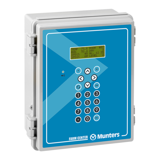
The Farm Center provides maximum capability with minimal complexity in programming and controlling up to 10 Farm Master units. Farm Center is the ultimate pig house controller. Equipped with an easy programming interface, it provides programmable outputs for all major features and a 4x20 character LCD that provides display feedback on the programming and device status. -
Page 9: Features
3.3 Features The following sections detail the Farm Center and Farm Master features. Farm Center features • Farm Master features • 3.3.1 Farm Center features Easy programming • LCD - 4x20 characters • Positioning scrollbar • Swift device and feature selection •... -
Page 10: Farm Center / Farm Master Network Connections
3.4 Farm Center / Farm Master network connections Figure 1: Farm Guard – Farm Center – Farm Master network © Munters AB, 2013... - Page 11 Figure 2: MUX – Farm Center – Farm Master network © Munters AB, 2013...
-
Page 12: Getting Started
Select. 4. Farm Center Cold Start: Plug in the controller and hold the delete key (DEL) for a few seconds until a Cold Start sign will appear. This action erases the memory completely and loads the default definitions. -
Page 13: Farm Center Keyboard
80.0 LEVEL NOTE The main screen shows basic information regarding rooms controlled by the Farm Center, depending on what equipment is plugged in. Other parameters like static pressure (PRESS), outside temperature (OUT), level, message and offset are also shown on the main screen when they are plugged in. -
Page 14: Hotkeys
• A dotted square indicates that there is no communication with the Farm Master. • NOTE Once communication is off there is no history accumulation in the Farm Center. A dotted lined square indicates N/A (not available). • 4.4 Hotkeys To activate the Hotkeys screens, press the Hotkey number while viewing the main screen. - Page 15 The temperature hot screen shows important information regarding the status of temperature sensors attached to the Farm Center. The average temperature (defined in table 6.6) is displayed on the upper left side and shows the average of temperature sensors T1 through T3. Table 6.2 enables the user to set the temperature sensor T3 as 'OUT' and therefore T3 presents the outside temperature.
- Page 16 Day number ('Day' column) • Minimum value measured on that day ('Min' column) • Average value calculated on the measured temperatures through the whole day ('Avg' column) • Maximum value measured on that day ('Max' column) • © Munters AB, 2013...
-
Page 17: Farm Center Setup
To reach the Farm Center Setup screen: 1. Go to Room key. 2. Press '0' and "Enter" from any of the main screens. The Farm Center setup is a procedure for customizing the Farm Center and Farm Master units to match the system. Farm Center ===COMM.===... - Page 18 The following table explains the parameters. Farm Center identity (Max-32). Define the Farm Center's unit number. If FARM CENTER only one Farm Center exists, the unit number is 1. Otherwise, the unit numbers are sequential (1, 2, 3,…). BAUDRATE Select communication baud rate with the PC.
-
Page 19: Control Menu
Limits: 0 - 999 • Target 0 – 40° C • Alarm low 0 – 40° C (without floating point) • Alarm high 0 – 40° C (without floating point) • © Munters AB, 2013... -
Page 20: Min. Max. Level
The third option provides the following; in extreme cold weather the min level ventilation might be decreased. For that, the user utilizes the Soft Min level that operates according to outside or inside temperature. For example: Target temperature = 23.3°C • Growth day = 1 • © Munters AB, 2013... -
Page 21: Soft Min Max Levels By Day Levels
To select the type of minimum/maximum go to system parameters and change the level control • (see page 21). 5.3 Humidity HUMIDITY #01 Target Delay (minute) Duration (sec) Band (%) Below Heat © Munters AB, 2013... -
Page 22: Static Pressure
Wind Delay: Static pressure is affected by wind. This definition is to ensure that an alarm is given • due to a stable change in pressure and not an accidental one, which may have been caused by a wind gust. © Munters AB, 2013... -
Page 23: System Parameters
Heat Lamp Diff Heat Offset ====MIN MAX==== Curve Level Control Soft Min Temp Soft Temp Band 10.0 ====PRESSURE==== Press Control ====LEVELS==== Inc Delay (s) Dec Delay (s) ====TUNNEL==== Tun Level Dif Below, Exit T.Out Dif, Exit 18.0 © Munters AB, 2013... -
Page 24: System Parameters Details
Soft Min Temp: choice whether to use the current inside temperature or the outside temperature to determine when to use the soft minimum. Default: OUT Soft Temp Band: diff below heat temperature to set temperature at which to enforce low temperature minimum ventilation level. Default: 10.0 © Munters AB, 2013... - Page 25 100% for 5 seconds. Default: No Min Motor1, 2, 3, 4 Spd: Safety speed fan operation delay. This is the Fan minimum speed to begin operation. Default: 30. © Munters AB, 2013...
-
Page 26: Control Mode
All alarms are disabled • A flashing message appears while displaying temperature • "E" In Farm Master and "Empty House" in Farm Center • Setting controller to Normal or Empty mode inserts an event to History/Event table. © Munters AB, 2013... -
Page 27: Device Menu
12345678 Diff The Farm Center provides up to 30 programmable ventilation levels. The usual way to program them is to start the first level with the least amount of air to be used. The full circles represent continuous fan operation. - Page 28 The following table is an example of a proper ventilation setting. Note that tunnel is not noticeable on the current table and is set according to the system parameter- 1 tunnel level. Level Tunnel Fans Diff © Munters AB, 2013...
-
Page 29: Variable Fan Levels
20% of the full power during off time in the cycle and will increase to 100% at on time. 6.3 Curtain Levels CURTAIN (%) Crt. 1 Crt. 2 Crt. 3 Crt. 4 Tun. inlet …3 Curtain Level Example Curtain (% Open) Level Tunnel Inlet Levels 1 thru 17 24..30 © Munters AB, 2013... -
Page 30: Circulation Fan
• If any of the four definitions above is set on 0, the circulation fan operates at any time or level according to the differential. 6.5 Cool Pad Cool Pad From Diff 08:00 20:00 10:00 18:00 © Munters AB, 2013... -
Page 31: Foggers
%RH: As long as the humidity + Band are below this level the foggers operates. • Foggers stop only at humidity level + band. (See figure below) • ON/OFF: (sec) On/Off cycle by seconds. • © Munters AB, 2013... -
Page 32: Light
FROM: (HH:MM) Start time. • TO: (HH:MM) End time. • To/From Temperature (From T./To T.): the temp range for extra system activity. • ON/OFF: (sec) On/off cycle by seconds. • This table consists of up to five programs. © Munters AB, 2013... -
Page 33: Time Clocks
Maximum Heat: Maximum heaters operation for safety measures. This parameter refers to both • var. heat 1 and var. heat 2. Default: 100% End Day: Set the last growth day for the Variable Heaters operation. Default: 0 • © Munters AB, 2013... -
Page 34: Management Menu
New Group: To start a new group, select YES under new group fragment and the controller will • automatically increase group number by one and set growth day to 1. CAUTION When starting a new group, History is deleted!!! Group No.: You can manually change the group number. • © Munters AB, 2013... -
Page 35: Alarm Setting
For example: IF the preset compensation is 1°C, the outside temperature is 24°C and alarm is set to 25°C, the controller adds the outside temperature to the comp, and the alarm will rise to 26. (25+1=26) © Munters AB, 2013... -
Page 36: Alarm Reset
GOLD DATA PLUG Read from Plug? SELECT SETTING NO◄ 1. Room No.1 2. Room No.2 Use the arrow keys to shift from NO to YES and press Enter <NO SETTING> to read from data plug. …8. © Munters AB, 2013... -
Page 37: Write To Plug
On the gold data plug, select no setting to create a new setting or overwrite an existing one. ENTER SETTING NAME Name: Room No. 1 To Change ARROWS ENTER, Abort MENU Press enter to load data to the plug. © Munters AB, 2013... -
Page 38: History Menu
TEMPERATURE #01 24.5 25.8 26.5 24.0 25.0 26.5 8.2 Humidity HUMIDITY AVG. 55.0 60.0 67.0 55.0 60.0 66.0 Sensors: Data collection for minimum, maximum and average in temperature and humidity for the • last 100 days. © Munters AB, 2013... -
Page 39: Water
DAY: Growth day. • DAILY: Daily consumption. • %CHANGE: % Change from previous day. • 8.5 Mortality MORTALITY #01 DAILY TOTAL DAY: Growth day. • DAILY: Daily mortality. • TOTAL: Mortality total since growth day one. • © Munters AB, 2013... -
Page 40: Heater
14. Sn.1 Out Rng: Sensor out of range 15. Sn.2 Out Rng 16. Sn.3 Out Rng 17. Sn. Not Def: Sensor not defined 18. Aux Alarm: Auxiliary alarm. 19. Press. Fail 20. Low S. Press. 21. High S. Press. © Munters AB, 2013... -
Page 41: Event
14:42 The events table is similar to the alarms table but without icons. For example: In the table above “menu #11” means that there was a change of settings in CONTROL menu 1, Temp Curve table. © Munters AB, 2013... -
Page 42: Calibration Menu
Value Press ENTER to calib 9.4 Water & Feed Water/Feed Water per pulse 0.1 Feed per pulse 1.0 The water and feed system operates on a pulse counting method. Enter the amount of feed/water per pulse. © Munters AB, 2013... -
Page 43: Installation Menu
• • • Curt. 1-4 open Curt. 1-4 close Tunnel open • • • Tunnel close Inlet open Inlet close • • • Light Feed Circulation • • • Extra system 1-3 Timer 1-5 • • © Munters AB, 2013... -
Page 44: Sensors Layout
1 Var. Heat 1 0.0 10.0 2 Var. Heat 2 0.0 10.0 3 Var. Fan 3 4 Var. Fan 4 Use the Round Arrows key to run through the list of outputs and press enter to select an output. © Munters AB, 2013... -
Page 45: Variable Speed Fan
Curtain Setup tells the controller how fast your curtains and side inlets CURTAIN OPEN CLS move. It needs this information to properly calculate automatic inlet Curtain1► advance as well as inlet and curtain positions. Curtain2 Curtain3 Curtain4 Tunnel Inlet © Munters AB, 2013... -
Page 46: Farm Master
11.4.1 Temperature sensor calibration 1. Use an accurate thermometer reference. 2. Place it near the temperature sensor. 3. Make sure that the inside temperature is stable. 4. Calibrate the temperature sensor immediately after reading. © Munters AB, 2013... -
Page 47: Calibration Procedure
Temperature sensors with the A/D counts blinking on the screen • Hu: humidity sensor A/D counts • Ai1-2: Analog inputs 1 to 2 • Prs: Pressure A/D counts • DG1-3: Digital inputs 1 to 3 • © Munters AB, 2013... -
Page 48: Specifications
Dimensions (L x W x H) 92.5 x 73 x 36 Ambient climate Operating temperature range 0º to + 50º C Storage temperature range -10º to + 70º C Indoor Applications The equipment is designed for use in indoor applications only! © Munters AB, 2013... -
Page 49: Mechanical Installation Guide
• Keep low voltage wires separate from high voltage wires. Use shielded wiring for low level signals. For buried wiring (building to building runs) use high • grade jell filled cables that are impervious to moisture. © Munters AB, 2013... -
Page 50: Mechanical Installation Guide
8. After installation is completed, operate the Farm Master for a few hours and re- check for proper operation. 13.4 Environmental protection Recycle raw materials instead of disposing as waste. The controller, accessories and packaging should be sorted for environmental-friendly recycling. The plastic components are labeled for categorized recycling. © Munters AB, 2013... -
Page 51: Metal Sheet Assembly Diagram
1. Drill holes in the three designated areas located in the back of the controller. 2. Mount the controller using the 3 screws provided in the small plastic bag. 3. Place the provided plastic caps on the screws. © Munters AB, 2013... - Page 52 Figure 4: Farm Master Wiring Diagram 1 (Analog Output, Power, Potentiometer, Relays, Variable speed, RHS-2) © Munters AB, 2013...
-
Page 53: Communication Wiring Diagrams
13.6 Communication wiring diagrams Figure 5: Farm Guard – Farm Center – Farm Master communication © Munters AB, 2013... - Page 54 Figure – Farm Center – Farm Master communication 6: MUX © Munters AB, 2013...
-
Page 55: Warranty
12 months of the delivery of the defective product. Munters has thirty days from the date of receipt in which to take action, and has the right to examine the product at the customer’s premises or at its own plant (carriage cost to be borne by... - Page 56 The use of non-original spare parts or incorrect assembly exonerates the manufacturer from all liability. Requests for technical assistance and spare parts can be made directly to the nearest Munters office. A full list of contact details can be found on the back page of this manual.
- Page 57 Munters Brasil Industria e Comercio Ltda, Phone +55 41 3317 5050, Canada Munters Corporation Mason, Phone +1 517 676 7070, China Munters Air Treatment Equipment (Beijing) Co. Ltd, Phone +86 10 80 418 000, Denmark Munters A/S, Phone +45 9862 3311, India...
Need help?
Do you have a question about the Farm Center and is the answer not in the manual?
Questions and answers