Table of Contents
Advertisement
Advertisement
Table of Contents
Troubleshooting

Subscribe to Our Youtube Channel
Related Manuals for Transition Networks SISPM1040-384-LRT-C


Summary of Contents for Transition Networks SISPM1040-384-LRT-C
- Page 1 Transition Networks Install Guide SISPM1040-384-LRT-C & SISPM1040-362-LRT SISPM1040-384-LRT-C and SISPM1040-362-LRT Managed Hardened PoE+ Switches SISPM1040-384-LRT-C SISPM1040-362-LRT Install Guide 33727 Rev. B 33727 Rev. B https://www.transition.com Page 1 of 49...
-
Page 2: Safety Warnings And Cautions
Anyone using this product in such an application without express written consent of an officer of Transition Networks does so at their own risk, and agrees to fully indemnify Transition Networks for any damages that may result from such use or sale. -
Page 3: Table Of Contents
Transition Networks Install Guide, SISPM1040-384-LRT-C & SISPM1040-362-LRT Contents Safety Warnings and Cautions ......................... 2 Introduction ........................... 5 Product Descriptions ........................5 Ordering Information ......................... 5 Manual Overview ........................5 Front Panel ..........................6 LED Descriptions ......................... 7 ALM (Alarm) LED ........................ 8 Front Panel 2-Position DIP Switch .................... - Page 4 Transition Networks Install Guide, SISPM1040-384-LRT-C & SISPM1040-362-LRT Troubleshooting PoE Problems ....................26 Related Manuals ........................28 Record Device and System Information ................... 29 Device Label and Packaging Label .................... 30 Features and Specifications ......................31 Key Features ..........................31 Software Features ........................33 MTBF Specifications .........................
-
Page 5: Introduction
Reset the switch to restore the switch to factory defaults • Use a Web browser to initially configure the switch • Troubleshoot the switch The SISPM1040-362-LRT and SISPM1040-384-LRT-C differ mainly in port count as noted in this manual. 33727 Rev. B https://www.transition.com Page 5 of 49... -
Page 6: Front Panel
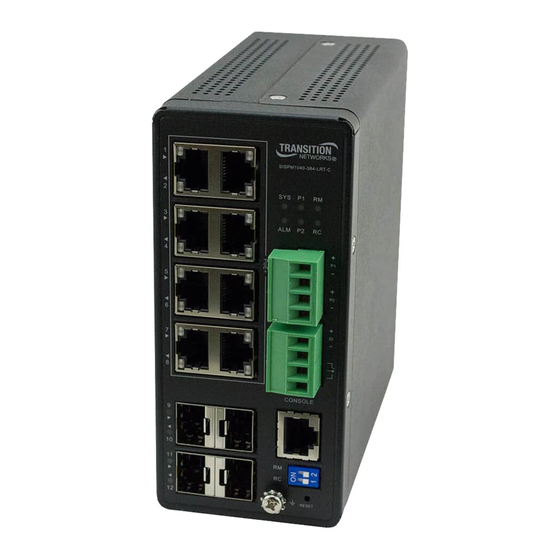
Transition Networks Install Guide, SISPM1040-384-LRT-C & SISPM1040-362-LRT Front Panel The switch front panel provides the ports, LEDs, DIP switch, RESET button, etc. as shown below. Figure 1: Front Panel 33727 Rev. B https://www.transition.com Page 6 of 49... -
Page 7: Led Descriptions
Transition Networks Install Guide, SISPM1040-384-LRT-C & SISPM1040-362-LRT LED Descriptions The front panel LEDs provide switch status as follows: Power LEDs (P1 and P2): indicate whether the switch is powered up correctly. SYS (System) LED: indicates if the system is ready or not. -
Page 8: Alm (Alarm) Led
Transition Networks Install Guide, SISPM1040-384-LRT-C & SISPM1040-362-LRT ALM (Alarm) LED The ALM (Alarm) LED lights if the monitored temperature or internal voltages are exceeded. Issue critical stage for High / Low Voltage alarm (Power A or B Voltage) Lit Alarm LED in RED Color if Test-point (max) < Volts or if Test-point (min) < Volts. - Page 9 Transition Networks Install Guide, SISPM1040-384-LRT-C & SISPM1040-362-LRT Check the port status by reading the LED behaviors per the table below. Table 4: Port Status LEDs Color State Description The port is enabled and has established a link to connected device, and the Green connection speed is 1000Mbps.
-
Page 10: Front Panel 2-Position Dip Switch
Transition Networks Install Guide, SISPM1040-384-LRT-C & SISPM1040-362-LRT Table 5: RM (Ring Master) and RC (Rapid-Chain) LEDs RM (Ring Master) RC (Rapid-Chain) disable disable Green Ring Master is Enabled Rapid-Chain (Active path) Amber Ring Slave is Enabled Rapid-Chain (Backup path) Error: Rapid-Chain Switch did not find the Blink Amber Error: More than one Master in this ring. -
Page 11: Rings Support
Note that Spanning Tree must be disabled for Rapid Ring operation. EPS and ERPS are standard protocols that can be used between various vendor switches. Rapid Rings protocols are only for Transition Networks switches that support Rapid Rings protocols. Notes: 1. -
Page 12: Reset Button
Transition Networks Install Guide, SISPM1040-384-LRT-C & SISPM1040-362-LRT RESET Button By pressing the RESET button for a specific amount of time, you can: Reset the Switch: to reboot and get the switch back to the previous configuration settings saved. Restore the Switch to Factory Defaults: to restore the original factory default settings back to the switch. -
Page 13: Installing The Switch
Transition Networks Install Guide, SISPM1040-384-LRT-C & SISPM1040-362-LRT 2. Installing the Switch Package Contents Verify that you have received the items below. Contact your sales representative if any item is missing. Please save the packaging for possible future use. • One Switch •... -
Page 14: Din Rail Mounting
Transition Networks Install Guide, SISPM1040-384-LRT-C & SISPM1040-362-LRT DIN Rail Mounting 1. Attach the DIN Rail mounting kit to chassis back panel. Insert screws and tighten with a screwdriver. Figure 2: Attaching DIN Rail Kit to the Switch 2. Insert the upper lip of the DIN rail into the DIN-rail mounting kit. Press the switch towards the DIN rail until it snaps into place. -
Page 15: Wall Mounting (Optional)
Transition Networks Install Guide, SISPM1040-384-LRT-C & SISPM1040-362-LRT Wall Mounting (Optional) See the WMBH-01 manual for more details. 1. Attach the wall mounting plates to rear panel of the chassis. Insert screws and tighten then with a screwdriver to secure the plates. -
Page 16: Connecting Ports
48~56V range to prevent damage to PDs. Installing SFP Modules On the SISPM1040-384-LRT-C, you can install or remove an SFP module from a SFP port without having to power off the switch. Note: Use UL Listed Transceiver SFPs rated 3.3Vdc, Laser Class 1. See the SFP manual for cautions and warnings. -
Page 17: Connecting To Dc Power
Transition Networks Install Guide, SISPM1040-384-LRT-C & SISPM1040-362-LRT Connecting to DC Power The upper Euro Block provides DC Power Inputs P1 and P2. See Power Supply Features and Specifications page 37. ATTENTION: This case must be earth grounded. No DC input may be earth grounded. -
Page 18: Connecting The Di/Do Relay Wires
Transition Networks Install Guide, SISPM1040-384-LRT-C & SISPM1040-362-LRT Connecting the DI/DO Relay Wires The lower Euro Block provides connection of the optional DI/DO Relay wires. Figure 9: Connecting DI/DO Relay Wires 1. Insert the negative (ground)/positive DI/DO Relay wires into the terminals, respectively. -
Page 19: Initial Switch Configuration
Transition Networks Install Guide, SISPM1040-384-LRT-C & SISPM1040-362-LRT 3. Initial Switch Configuration Initial Switch Configuration via Web Browser After powering up the switch for the first time, you can perform the initial switch configuration using a web browser. For managing other switch features, refer to the Web User Guide for details. -
Page 20: Initial Switch Configuration Via Cli
Transition Networks Install Guide, SISPM1040-384-LRT-C & SISPM1040-362-LRT Connect the PC to any port on the switch using a standard Ethernet cable, and check the port LED on the switch to make sure the link status of the PC’s is OK. -
Page 21: Troubleshooting
Transition Networks Install Guide, SISPM1040-384-LRT-C & SISPM1040-362-LRT 4. Troubleshooting Basic Troubleshooting Make sure your switch model supports the feature or function attempted; see chapter 5. Features and Specifications on page 31. Verify the install process; see chapter 2. Installing the Switch on page 13. -
Page 22: Troubleshooting Led Indications
Transition Networks Install Guide, SISPM1040-384-LRT-C & SISPM1040-362-LRT Troubleshooting LED Indications The following table provides information to troubleshoot problems by taking actions based on the symptom. Symptom Possible Cause Suggested Solutions 1. Check if correct power cord is connected firmly to the switch and to the DC outlet socket. -
Page 23: Led Summary
Transition Networks Install Guide, SISPM1040-384-LRT-C & SISPM1040-362-LRT LED Summary Category Color Function System status LED: LED Off: All Power is off. Global Green Green Lit: Switch FW Boot up is Ready. Green blinking: System is booting. Power 1 LED: Global Green LED Off: Power 1 off. -
Page 24: Poe Modes And Compliance
Transition Networks Install Guide, SISPM1040-384-LRT-C & SISPM1040-362-LRT PoE Modes and Compliance PoE Deployment Environments A and B IEEE802.3at-2009 defines two deployment environments in section 33.4.1: Environment A: when both PSE and PD are located indoors, inside the same building. In this environment, there has to be electrical isolation between the PoE circuitry and the data circuitry inside a PSE. - Page 25 • 802.3af/at "compatible" PDs typically can provide power using only Mode B. Typical PD Power Requirements 1.8 Watts: Transition Networks’ M/GE-ISW-SFP-01-PD (Class 1 Powered Device (0.44 Watts - 3.84 □ Watts). 13W: IP Camera, VoIP Phone, Wireless Access Point, Networked Audio.
-
Page 26: Troubleshooting Poe Problems
3. For outdoor PoE applications, we recommend using Transition Networks' SI-IES-1200-LRT Unmanaged Hardened PoE+ Injector or SI-IES-111D-LRT Unmanaged Hardened PoE+ Injector/Converter Use of any other PoE injector will void the user's warranty and could create a fire or shock hazard. - Page 27 Transition Networks Install Guide, SISPM1040-384-LRT-C & SISPM1040-362-LRT 7. Verify that the PSE switch power budget can power the PD. If the switch power budget is depleted, additional PDs will not power-on when connected to a PoE port. Verify that the switch power budget (available PoE) is not depleted before or after the PD is connected.
-
Page 28: Related Manuals
(unplug the switch, wait at least three seconds, then plug it back in. This will ensure a total system reset that should restore normal operation. Check if related features (LLDP mode, CDP mode) are enabled. See the Transition Networks PoE Brochure more information. -
Page 29: Record Device And System Information
Describe any action(s) already taken to resolve the problem (e.g., changing mode, rebooting, etc.): ________________ ________________________________________________________________________________________________________________________ ________________________________________________________________________________________________________________________ ________________________________________________________________________________________________________________________ The serial and revision numbers of all involved Transition Networks products in the network: ______________________ ________________________________________________________________________________________________________________________ ________________________________________________________________________________________________________________________ Describe your network environment (layout, cable type, etc.): ________________________________________________________... -
Page 30: Device Label And Packaging Label
Transition Networks Install Guide, SISPM1040-384-LRT-C & SISPM1040-362-LRT Device Label and Packaging Label In addition to the device CLI and Web GUI, you can find device information on the device Serial Label (left) and box Serial Label (right). Serial Label on Unit (left) Serial Label on Box (right) 33727 Rev. -
Page 31: Features And Specifications
SISPM1040-362-LRT: Managed Hardened PoE+ Switch; provides (4) 10/100/1000Base-T PoE+ + (2) 10/100/1000Base-T RJ-45 + (2) 100/1000Base-X SFP Ports. SISPM1040-384-LRT-C: Managed Hardened PoE+ Switch; provides (8) 10/100/1000Base-T PoE+ RJ45 ports + (4) 100/100Base-X SFP ports and one RJ45 Console port. Feature... - Page 32 Transition Networks Install Guide, SISPM1040-384-LRT-C & SISPM1040-362-LRT Feature SISPM1040-362-LRT SISPM1040-384-LRT-C Hardware Performance Forwarding Capacity (Mpps) 11.904 17.586 Switching Capacity (Gbps) Mac Table (K) Jumbo Frames (Bytes) 9216 9216 SISPM1040-362-LRT Environmental Range SISPM1040-384-LRT-C -40 to 167F -40 to 167F Operating Temperature...
-
Page 33: Software Features
Transition Networks Install Guide, SISPM1040-384-LRT-C & SISPM1040-362-LRT Software Features SISPM1040-384-LRT-C and SISPM1040-362-LRT Ring Management Rapid Ring Enables self-recover time in less than 20ms. ITU-T G.8031 Supports ITU-T G.8031 Ethernet Linear Protection Switching (EPS). ITU-T G.8032 Supports ITU-T G.8032 Ethernet Ring Protection Switching (ERPS). - Page 34 Transition Networks Install Guide, SISPM1040-384-LRT-C & SISPM1040-362-LRT SISPM1040-384-LRT-C and SISPM1040-362-LRT Used to support a Layer 2 multicast domain of snooping switches in the absence of a IGMP Querier multicast router. IGMP snooping with proxy reporting or report suppression actively filters IGMP packets IGMP Proxy in order to reduce load on the multicast router.
- Page 35 Transition Networks Install Guide, SISPM1040-384-LRT-C & SISPM1040-362-LRT Quality of Service Hardware Queue Supports 8 hardware queues Strict priority and weighted round-robin (WRR). Scheduling Queue assignment based on DSCP and class of service. Port based. 802.1p VLAN priority based. Classification IPv4/IPv6 precedence / DSCP based.
-
Page 36: Mtbf Specifications
Transition Networks Install Guide, SISPM1040-384-LRT-C & SISPM1040-362-LRT Network Time Protocol for clock synchronization between computer systems over packet-switched. HTTP/HTTPs; SSH DHCP Client/ DHCPv6 Client Other Management Cable Diagnostics, Ping, Syslog IPv6 Management Power over Ethernet (PoE) Port Configuration Supports per port PoE configuration function. -
Page 37: Shared Features
Transition Networks Install Guide, SISPM1040-384-LRT-C & SISPM1040-362-LRT Shared Features Primary Power Supply - DC Input Voltage Voltage and Frequency SISPM1040-384-LRT-C and SISPM1040-362-LRT 54 VDC dual inputs DC Nominal 48 to 57 VDC DC Operating Range Requires >48 VDC for PoE IEEE 802.3af (Max. 15.4W output) Requires >54 VDC for PoE+ IEEE 802.3at (Max. -
Page 38: Shared Certifications And Compliance
Transition Networks Install Guide, SISPM1040-384-LRT-C & SISPM1040-362-LRT Shared Certifications and Compliance CE, FCC Part 15 EN61000-4-2, EN61000-4-3,EN-61000-4-4, EN61000- 4-5, EN61000-4-6,EN61000-4-8 Free fall IEC60068-2-32 Shock IEC60068-2-27 Vibration IEC60068-2-6 Safety IEC60950-1 Hazardous UL Class 1/Div 2 Location Railway EN50155 Compliant, EN50121-4 Compliant... -
Page 39: Power Supply Features And Specifications
Transition Networks Install Guide, SISPM1040-384-LRT-C & SISPM1040-362-LRT Power Supply Features and Specifications The Industrial Power Supplies (25104 and 25105) are optional accessories (sold separately). 25104 Input: 85-264 VAC, 124-370 VDC. Output: 48~55 VDC, 5.0A, 240 Watts. □ 25105 Input: 85-264 VAC, 124-370 VDC Output: 48~55 VDC, 2.5A, 120 Watts. -
Page 40: Industrial Power Supply 25104
Transition Networks Install Guide, SISPM1040-384-LRT-C & SISPM1040-362-LRT Industrial Power Supply 25104 Output Output Voltage 48VDC Current Rating Power Rating 240 Watts Ripple & Noise Max 120mVp-p Voltage Range 48~55VDC Voltage Tolerance ±1.0% Line Regulation ±0.5% Load Regulation ±1.0% Setup, Rise Time... -
Page 41: Power Supply Built-In Dc Ok Relay Contact
Transition Networks Install Guide, SISPM1040-384-LRT-C & SISPM1040-362-LRT Power Supply Built-in DC OK Relay Contact 1 2 3 4 5 6 The power supply’s DC OK relay contact is provided below. Contact Closed PSU turns on / DC OK. Contact Open PSU turns off / DC Fail. -
Page 42: Power Supply Dimensions - 25104 (Sdr-240-48)
Transition Networks Install Guide, SISPM1040-384-LRT-C & SISPM1040-362-LRT Power Supply Dimensions - 25104 (SDR-240-48) Dimensions (in mm) - 25104 (SDR-240-48) 33727 Rev. B https://www.transition.com Page 42 of 43... -
Page 43: Regulatory And Safety Information
Transition Networks Install Guide, SISPM1040-384-LRT-C & SISPM1040-362-LRT 6. Regulatory and Safety Information Compliance and Safety Statements FCC-CLASS A: This equipment has been tested and found to comply with the limits for a Class A computing device pursuant to Subpart J of part 15 of FCC Rules, which are designed to provide reasonable protection against such interference when operated in a commercial environment. -
Page 44: High Risk Activities Disclaimer
Nuclear Facilities, Aircraft Navigation or Aircraft Communication Systems, Air Traffic Control, Life Support, or Weapons Systems ("High Risk Activities"). Transition Networks and its supplier(s) specifically disclaim any expressed or implied warranty of fitness for such High Risk Activities. -
Page 45: Electrical Safety Warnings
Transition Networks Install Guide, SISPM1040-384-LRT-C & SISPM1040-362-LRT Electrical Safety Warnings Electrical Safety IMPORTANT: This equipment must be installed in accordance with safety precautions. Elektrische Sicherheit WICHTIG: Für die Installation dieses Gerätes ist die Einhaltung von Sicherheitsvorkehrungen erforderlich. Elektrisk sikkerhed VIGTIGT: Dette udstyr skal installeres i overensstemmelse med sikkerhedsadvarslerne. -
Page 46: Class I Division 2
Transition Networks Install Guide, SISPM1040-384-LRT-C & SISPM1040-362-LRT Class I Division 2 The product has been evaluated to the requirements of UL and the Canadian National Standard: USL – ANSI/ISA 12.12.01-2015, Nonincendive Electrical Equipment for Use in Class I and II, Division 2 and Class III, Divisions 1 and 2 Hazardous (Classified) Locations, Approved 21 August 2015. -
Page 47: Service, Warranty & Tech Support
In no event shall Transition Networks be liable for incidental or consequential damages, costs, or expenses arising out of or in connection with the performance of the product delivered hereunder. -
Page 48: Contact Us
Transition Networks reserves the right to charge a $50 fee for all testing and shipping incurred, if after testing, a return is classified as “No Problem Found.”... - Page 49 10900 Red Circle Drive Minnetonka, MN 55343 USA tel: +1.952.941.7600 | toll free: 1.800.526.9267 | fax: 952.941.2322 Copyright© 2017-2018 Transition Networks. All rights reserved. Printed in the U.S.A. SISPM1040-384-LRT-C and SISPM1040-362-LRT Install Guide, 33727 Rev. B 33727 Rev. B https://www.transition.com...
Need help?
Do you have a question about the SISPM1040-384-LRT-C and is the answer not in the manual?
Questions and answers