Table of Contents
Advertisement
Quick Links
Advertisement
Table of Contents

Related Manuals for Transition Networks SISPM1040-384-LRT-C


Summary of Contents for Transition Networks SISPM1040-384-LRT-C
- Page 1 Transition Networks Install Guide, SISPM1040-362-LRT and SISPM1040-384-LRT-C SISPM1040-384-LRT-C and SISPM1040-362-LRT Managed Hardened PoE+ Switches SISPM1040-384-LRT-C SISPM1040-362-LRT Install Guide 33727 Rev. G 33727 Rev. G https://www.transition.com Page 1 of 51...
-
Page 2: Safety Warnings And Cautions
Anyone using this product in such an application without express written consent of an officer of Transition Networks does so at their own risk and agrees to fully indemnify Transition Networks for any damages that may result from such use or sale. -
Page 3: Table Of Contents
Transition Networks Install Guide, SISPM1040-362-LRT and SISPM1040-384-LRT-C Contents Safety Warnings and Cautions ......................2 1. Introduction ............................ 5 Product Descriptions ........................5 Ordering Information ......................... 5 Manual Overview ........................6 Front Panel ..........................6 LED Descriptions ......................... 7 Front Panel 2-Position DIP Switch .................... 10 Rings Support ........................... - Page 4 Transition Networks Install Guide, SISPM1040-362-LRT and SISPM1040-384-LRT-C PoE Modes and Compliance ..................... 27 Troubleshooting PoE Problems ....................29 Related Manuals ........................31 Device Label and Packaging Label .................... 31 Record Device and System Information ................... 32 5. Features and Specifications ......................33 Key Features ..........................
-
Page 5: Introduction
It can supply up to 30 Watts per port on all four PoE ports simultaneously. The SISPM1040-362-LRT and SISPM1040-384-LRT-C differ mainly in port count as noted in this manual. These switches include embedded Device Management System (DMS) software that provides the advanced tools necessary for total management of all IP addressable devices. -
Page 6: Manual Overview
Transition Networks Install Guide, SISPM1040-362-LRT and SISPM1040-384-LRT-C Manual Overview This manual describes how to install, configure, and troubleshoot the PoE+ Switches, including how to: • Install the switch • Check switch status by reading the LED indicators • Reset the switch to restore the switch to factory defaults •... -
Page 7: Led Descriptions
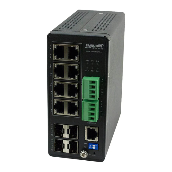
Transition Networks Install Guide, SISPM1040-362-LRT and SISPM1040-384-LRT-C LED Descriptions The front panel LEDs provide switch status as follows: SYS (System) LED: indicates if the system is ready or not. P1 and P2 (Power LEDs): indicate whether the switch is powered up correctly. - Page 8 Transition Networks Install Guide, SISPM1040-362-LRT and SISPM1040-384-LRT-C ALM (Alarm) LED The ALM (Alarm) LED lights if the monitored temperature or internal voltages are exceeded. Issue critical stage for High / Low Voltage alarm (Power A or B Voltage) Lit Alarm LED in RED Color if Test-point (max) < Volts or if Test-point (min) < Volts.
- Page 9 Transition Networks Install Guide, SISPM1040-362-LRT and SISPM1040-384-LRT-C Check the port status by reading the LED behaviors per the table below. Table 4: Port Status LEDs Color State Description The port is enabled and has established a link to the connected device, and Green the connection speed is 1000Mbps.
-
Page 10: Front Panel 2-Position Dip Switch
Transition Networks Install Guide, SISPM1040-362-LRT and SISPM1040-384-LRT-C Table 5: RM (Ring Master) and RC (Rapid-Chain) LEDs RM (Ring Master) RC (Rapid-Chain) disable disable Green Ring Master is Enabled Rapid-Chain (Active path) Amber Ring Slave is Enabled Rapid-Chain (Backup path) Error: Rapid-Chain Switch did not find the... -
Page 11: Rings Support
Note that Spanning Tree must be disabled for Rapid Ring operation. EPS and ERPS are standard protocols that can be used between various vendor switches. Rapid Rings protocols are only for Transition Networks switches that support Rapid Ring protocols. Notes: 1. -
Page 12: Reset Button
Transition Networks Install Guide, SISPM1040-362-LRT and SISPM1040-384-LRT-C RESET Button By pressing the RESET button for a specific amount of time, you can: Reset the Switch: to reboot and get the switch back to the previous configuration settings saved. Restore the Switch to Factory Defaults: to restore the original factory default settings back to the switch. -
Page 13: Installing The Switch
Transition Networks Install Guide, SISPM1040-362-LRT and SISPM1040-384-LRT-C 2. Installing the Switch Package Contents Verify that you have received the items below. Contact your sales representative if any item is missing. Please save the packaging for possible future use. • One Switch •... -
Page 14: Din Rail Mounting
Transition Networks Install Guide, SISPM1040-362-LRT and SISPM1040-384-LRT-C DIN Rail Mounting 1. Attach the DIN Rail mounting kit to chassis back panel. Insert screws and tighten with a screwdriver. Figure 2: Attaching DIN Rail Kit to the Switch 2. Insert the upper lip of the DIN rail into the DIN-rail mounting kit. Press the switch towards the DIN rail until it snaps into place. -
Page 15: Wall Mounting (Optional)
Transition Networks Install Guide, SISPM1040-362-LRT and SISPM1040-384-LRT-C Wall Mounting (Optional) See the WMBH-01 manual for more details. 1. Attach the wall mounting plates to rear panel of the chassis. Insert screws and tighten then with a screwdriver to secure the plates. -
Page 16: Connecting Copper Ports
48~56V range to prevent damage to PDs. Installing SFP Modules On the SISPM1040-384-LRT-C, you can install or remove an SFP module from a SFP port without having to power off the switch. Note: Use UL Listed Transceiver SFPs rated 3.3Vdc, Laser Class 1. See the SFP manual for cautions and warnings. -
Page 17: Connecting The Di/Do Relay Wires
Transition Networks Install Guide, SISPM1040-362-LRT and SISPM1040-384-LRT-C Connecting the DI/DO Relay Wires The lower Euro Block (Terminal Block) provides connection of the optional DI/DO Relay wires. Figure 9: Connecting DI/DO Relay Wires 1. Insert the negative (ground)/positive DI/DO Relay wires into the terminals, respectively. - Page 18 Transition Networks Install Guide, SISPM1040-362-LRT and SISPM1040-384-LRT-C Digital Input and Digital Output Use Case The switch supports Digital Input and Digital Output. The Digital Input enables the switch to detect and log external device status (such as door intrusion detector). The Digital Output could be used to tell administrators if the switch port shows link down, link up or power failure.
-
Page 19: Connecting To Dc Power
Transition Networks Install Guide, SISPM1040-362-LRT and SISPM1040-384-LRT-C An external alarm device (e.g., power supply or IP camera) can activate this input pin. Level 0 (Low): 0V to 6V Level 1 (High): 10V to 24V For DO, it’s similar but the switch is the alarm device, when the switch has temperature or voltage alarm, it will trigger the digital output (24V/1A) to the external device such as a contact relay. -
Page 20: Power Connection
Transition Networks Install Guide, SISPM1040-362-LRT and SISPM1040-384-LRT-C Power Connection ATTENTION: This case must be earth grounded. No DC input may be earth grounded. Use Isolated Power Supply. Negative DC voltage is not supported. Recommended Best Practice: First, connect the power supply to the switch while powered off. Then connect the power supply to power, otherwise product failure may occur.
Need help?
Do you have a question about the SISPM1040-384-LRT-C and is the answer not in the manual?
Questions and answers