
Related Manuals for NoiseKen IJ-02


Summary of Contents for NoiseKen IJ-02
- Page 1 INSTRUCTION MANUAL IMPULSE NOISE SIMULATOR FILTER & INJECTION UNIT IJ-02/IJ-03 MODEL Noise Laboratory Co., Ltd. INS-IJ (3.05 EDITION) AEB000322-00E-2F...
- Page 2 NOTICE The contents of this booklet are subject to change without prior notice. No part of this booklet may be reproduced or transferred, in any form, for any purpose, without the permission of Noise Laboratory Co., Ltd. The contents of this booklet have been thoroughly checked. However, if a doubtful point, an error in writing or a missing is found, please contact us.
-
Page 3: Important Safety Precautions
IMPORTANT SAFETY PRECAUTIONS Thoroughly understand the following precautions before use, as they are important matters for handling this unit in safety. This unit cannot be used in an explosive area, fire prohibited area, etc. Use of this unit in such an area is liable to cause combustion or ignition. A person who has a pacemaker on should not operate this unit and also should not enter the area where it is operating. - Page 4 MEMO...
-
Page 5: Application Form For Instruction Manual
APPLICATION FORM FOR INSTRUCTION MANUAL We place an order for an instruction manual. Model: Serial No.: Applicant: Company name: Address: Department: Person in charge: Tel No.: Fax No. Cut off this page “APPLICATION FORM FOR INSTRUCTION MANUAL” from this volume and keep it for future use with care. When an INSTRUCTION MANUAL is required, fill in the above Application Form and mail or fax it to the following sales department of our company. - Page 6 MEMO...
-
Page 7: Table Of Contents
CONTENTS IMPORTANT SAFETY PRECAUTIONS ................1 APPLICATION FORM FOR INSTRUCTION MANUAL ..........3 CONTENTS ........................... 5 BASIC SAFETY PRECAUTIONS FOR THIS SIMULATOR ............6 Warning signs and their meanings ................6 Basic safety precautions ....................0 When warning label is missing ..................8 FEATURES: CAPABILITIES OF THIS UNIT ................ -
Page 8: Basic Safety Precautions For This Simulator
BASIC SAFETY PRECAUTIONS FOR THIS SIMULATOR Warning signs and their meanings a warning. Means If such a danger is not avoided, a potential danger which may result in a death or serious injury will be caused. a caution. Means If such a danger is not avoided, a potential danger which may result in a minor or medium degree of injury will be caused. - Page 9 The AC INPUT (AC inlet) terminal on the rear panel has a conductor for safety grounding connection. This unit shall be connected to a properly grounded service outlet through the AC INPUT. When this unit is not grounded through the AC INPUT, PE terminal positioned next to it shall be used.
-
Page 10: When Warning Label Is Missing
Using solvents may spoil the appearance. [Precautions for handling] 24. The coaxial connectors used for this unit is of NoiseKen original design. Use of other type of connectors may cause electric shock hazards or malfunctions of the unit. -
Page 11: Features: Capabilities Of This Unit
FEATURES: CAPABILITIES OF THIS UNIT By using this unit in combination with the control & pulse generating Unit (INS-200AX, INS-300AX and INS-400AX), you can conduct a noise test for EUT with power capacity of up to AC 240V (single/3-phase)/DC 65V, 30A. Switching of injection phase and common/normal mode is automatic. -
Page 12: Standard Accessories
STANDARD ACCESSORIES This unit is supplied with the following standard accessories. ■Coaxial cable (1m x 1 pc.)................Fig.6-1-A It is used to connect to Control & Pulse Generating Unit. ■Coaxial cable for terminal resistance.. (18cm x 1 pc.)........Fig.6-1-B It is used to connect terminal resistance with injection IN. ■Output terminal (Red x 4 pcs.).............. - Page 13 Fig. 6-1 Standard accessories...
-
Page 14: Name And Function Of Each Part
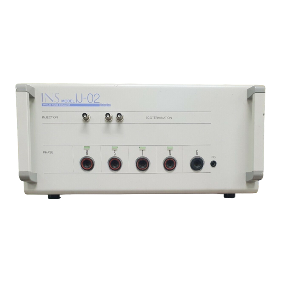
NAME AND FUNCTION OF EACH PART “Pulse injection connector”, “50 Ω terminal resistance”, “output indicating LED” and “output connector” are arranged on the front side of this unit. “Control connector”, “operating power connector and fuse”, “terminal base for EUT” and “breaker” are arranged on the rear side of the unit. - Page 15 Fig. 7-1 Front view of the unit ① ② ③ ⑦ ④ ⑧ ⑨ ⑤ ⑩ ⑥ ⑪ ⑫...
- Page 16 ■ ■ ■ ■ Rear side (Fig. 7-2) ① TO CONTROL UNIT (Control connector) It connects to TO INJECTION UNIT of Control & Pulse Generating Unit. Use the control cable (standard accessory) of Control & Pulse Generating Unit for connection. ②...
- Page 17 Fig. 7-2 Rear view of the unit ① ⑦ ⑤ ③ ② ④ ⑥...
-
Page 18: Operation
OPERATION When conducting a noise test using this Unit, follow the operating precautions. For how to set each test screen, refer to the instruction manual (User's guide). Operation with this unit used in combination with the control & pulse generating unit is described below: ■... -
Page 19: Connections
CONNECTIONS ■ How to connect to FG terminal for INS-AX Series INS-AX Series has a floating structure equipped with FG terminal and G terminal. The function of these terminals and how to connect to them are explained below: FG terminal is GND potential for chassis. INS-○○○AX has one FG terminal on the rear panel. - Page 20 Connect “TERMINATION” (terminal resistance) and “INJECTION” of Filter & ① Injection Unit with the coaxial cable for terminal resistance (standard accessory). Connect “PULSE OUT” of Control & Pulse Generating Unit and “TERMINATION” of ② Filter & Injection Unit with the coaxial cable for injection (standard accessory) of Filter &...
-
Page 21: Performance And Specifications
This unit is designed to inject noise to AC line of EUT by using in combination with Control & Pulse Generating Unit. Table 1 shows the performance and specifications of this unit. Table 9-1 Performance and specifications of this unit Item IJ-02 IJ-03 Remarks AC240V AC240V... -
Page 22: How To Check The Waveform
HOW TO CHECK THE WAVEFORM The output waveform shall be verified with the units placed in the same set-up as the actual test run and with the supplied output terminals connected to either Phase Output Connector, by using an oscilloscope and high voltage probe. Equipment to be required •... -
Page 23: Warranty
WARRANTY Servicing terms The following terms are applicable to servicing by Noise Laboratory Co., Ltd., (hereafter referred to as the Company) provided to maintain the intended performance of its products. 1. Scope The following terms shall apply only to products made by the Company. 2. - Page 24 Limited warranty Noise Laboratory Co., Ltd. (hereafter referred to as the Company) warrants its products to be free from defects in materials and workmanship under normal use and service for a period of one year from date of delivery. In the event of failure of a product covered by this warranty, the Company will repair the product or may, at its option, replace it in lieu of repair without charge.
-
Page 25: Maintenance
MAINTENANCE When repair, maintenance or internal adjustment of the unit is required, a qualified service engineer takes charge of such work. Maintenance on the user side is restricted to the outside cleaning and functional check of the unit. When checking or replacing the fuse, turn off the switch of the unit and disconnect the plug socket beforehand. -
Page 26: Noise Laboratory Support Network
NOISE LABORATORY SUPPORT NETWORK If a symptom that seems a trouble is found, check the symptom against the following check sheet and inform the model name and serial Number of the product together with the symptom to Noise Laboratory or our nearest sales agent in your area. - Page 27 Noise Laboratory Co., Ltd. PRINTED IN JAPAN...
Need help?
Do you have a question about the IJ-02 and is the answer not in the manual?
Questions and answers