Table of Contents
Advertisement
Quick Links
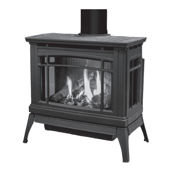
Westley-820/821
F R E E S T A N D I N G G A S F I R E P L A C E
OWNER'S MANUAL
WARNING:
If the information in this manual is not followed exactly, a
fire or explosion may result causing property damage, personal injury
or loss of life. Installation and service must be performed by a qualified
installer, service agency or the gas supplier.
C#4001609
CERTIFIED TO/CERTIFIÉ AUX: ANSI Z21.88 / CSA2.33 / CSA 2.17
50-4127
Version Française: www.enviro.com/fr.html
Advertisement
Table of Contents

Related Manuals for Enviro Westley-820


Summary of Contents for Enviro Westley-820
- Page 1 Installation and service must be performed by a qualified installer, service agency or the gas supplier. C#4001609 CERTIFIED TO/CERTIFIÉ AUX: ANSI Z21.88 / CSA2.33 / CSA 2.17 50-4127 Version Française: www.enviro.com/fr.html...
-
Page 2: Safety Precautions
Safety Precautions WARNING: FIRE OR EXPLOSION HAZARD Failure to follow safety warnings exactly could result in serious injury, death, or property damage. - Do not store or use gasoline or other flammable vapors and liquids in the vicinity of this or any other appliance. - WHAT TO DO IF YOU SMELL GAS •... - Page 3 Safety Precautions FOR SAFE INSTALLATION AND OPERATION OF YOUR “ENVIRO” HEATER, PLEASE CAREFULLY READ THE FOLLOWING INFORMATION: • All ENVIRO gas-fired appliances must be installed in • A barrier designed to reduce the risk of burns from the accordance with their instructions. Carefully read all the hot veiwing glass is provided with this appliance and shall instructions in this manual first.
-
Page 4: Table Of Contents
Table of Contents Safety Precautions......................2 Table of Contents......................4 Codes And Approvals....................5 Specifications......................6 Dimensions.....................6 Rating Label Location..................6 Operating Instructions....................7 Lighting Instructions..................7 Pilot Light......................8 Air Shutter......................8 Burner Lighting....................9 Blower Speed....................10 Normal Sounds During Operation...............10 Maintenance and Service.....................10 Routine Maintenance..................10 Cleaning Decorative Surfaces................10 Cleaning the Glass...................11 Cleaning the Firebox..................11 Replacing the Glass..................11... -
Page 5: Codes And Approvals
After the unit has gone through the first burn, turn the unit off including the pilot, let the unit get cold then remove the glass door and clean it with a good gas fireplace glass cleaner, available at your local ENVIRO dealer. -
Page 6: Specifications
Specifications imensions 26 3/4" [67.9 cm] 5" [12.7 cm] 15 15/16" 25 15/16" [40.5 cm] [65.9 cm] 27 1/2" [69.9 cm] 19 9/16" [49.7 cm] Figure 1. Westley Dimensions & L ating abeL ighting nstRuctions ocation The rating label and lighting instructions are located on a plate hanging on the back of of the unit. -
Page 7: Operating Instructions
Operating Instructions For Your Safety, Read Safety Precautions And Lighting Instructions Before Operating WARNING: IF YOU DO NOT FOLLOW THESE INSTRUCTIONS EXACTLY A FIRE OR EXPLOSION MAY RESULT, CAUSING PROPERTY DAMAGE, PERSONAL INJURY OF LOSS OF LIFE. ighting anD uRning nstRuctions FOR YOUR SAFETY READ BEFORE LIGHTING WARNING... -
Page 8: Pilot Light
PILOT. While pushing the gas control knob in, press the piezo ignitor several times until the pilot light starts. Hold the control knob down: Westley-820 Models - Hold for approximately 30 seconds. Westley-821 Models - Hold until an audible “BEEP” is emitted from the valve (up to 1 minute). -
Page 9: Burner Lighting
After the unit has gone through the first burn, turn the unit OFF, including the pilot, and let the unit get completely cold. Then remove the glass and clean it with a good gas fireplace glass cleaner, available at your local Enviro dealer. See “M aIntenance ”... -
Page 10: Blower Speed
Operating Instructions LoweR sPeeD The blower will come on only when the fireplace is up to temperature (approximately 15 minutes). The speed of the fan can be changed by turning the fan control knob. The blower will continue to operate automatically after the unit has been shut off (approximately 25 minutes).To turn the blower off, turn the knob COUNTER CLOCKWISE until it “clicks”... -
Page 11: Cleaning The Glass
The glass must be purchased from an ENVIRO dealer. No substitute materials are allowed. Remove the door (see page 12). The replacement glass will come with a new gasket installed. Remove any silicone remnants from the door. -
Page 12: Cast Door Removal
Maintenance And Service emovaL The cast door on the Westley needs to be removed whenever access to the firebox is required. First the Westley must be turned Cast Top off and allowed to fully cool. Next, remove the Cast Top as shown in Figure 10 by simply lifting up. -
Page 13: Burner Removal
Maintenance And Service uRneR emovaL The burner may need to be removed for a few reasons, including cleaning under the burner, converting the unit to a different gas type, or to replace the burner altogether. Proceed only when the unit has completely cooled down. -
Page 14: Fuel Conversion
Maintenance And Service onveRsion TO BE INSTALLED BY A QUALIFIED SERVICE AGENCY ONLY Please read and understand these instructions before installing. Warning: This conversion kit shall be installed by a qualified service agency in accordance with the manufacturer’s instructions and all applicable codes and requirements of the authority having jurisdiction. - Page 15 Maintenance And Service 7. Convert the SIT gas valve: a) Remove the black protection cap from the HI/LO knob by hand shown in Figure 16. b) Insert a ” or 4 mm Allen wrench into the hexagonal key-way of the screw (see Figure 17), rotate it counter-clockwise until it is free and extract it.
- Page 16 Maintenance And Service 8. LP Conversions Only: Install the supplied LP Air steel air deflector onto the burner tray Deflector as shown below (Figure 20) using a T20 screwdriver. 9. Reinstall the burner, tray, log set, and glass door. Also refer to s econDary nstallatIon in your Owner’s...
-
Page 17: Initial Installation
Initial Installation QUALIFIED INSTALLERS ONLY ntRoDuction This section of the owner’s manual is for the use of qualified technicians only. Fireplace placement, hearths, and venting terminations will be covered, as well as the gas and electrical systems. There are several installation safety guidelines that must be adhered to. Please carefully read the safety precautions at the front of this manual. -
Page 18: Direct Vent
Initial Installation QUALIFIED INSTALLERS ONLY iRect WARNING: This appliance has been designed to draw room air for proper heat circulation from the bottom of the unit, and out the top front. Blocking or modifying these openings in any way can create hazardous situations. The vent length for the Westley must be between 36”... - Page 19 Initial Installation QUALIFIED INSTALLERS ONLY WARNING: Do not mix parts from different vent manufacturers’ systems. EXCEPTION TO WARNING: This product has been evaluated by Intertek for using a DirectVent Pro starting collar in conjunction with other venting systems. Use of this system with the DirectVent Pro starting collar is deemed acceptable and does not affect the Intertek listing of the appliance.
-
Page 20: Vent Termination Restrictions
Initial Installation QUALIFIED INSTALLERS ONLY eRmination estRictions Fixed Closed Fixed Openable Closed Openable Termination Cap Air Supply Inlet Restriction Zone Gas Meter (Termination not allowed) Figure 24. Vent Termination Restrictions, refer to Table 5. Table 5: Vent termination clearances. Letter Canadian Installation US Installation Description... -
Page 21: Exhaust Restrictor Setting
Initial Installation QUALIFIED INSTALLERS ONLY xhaust estRictoR etting The Westley has an internal exhaust restrictor that can adjusted externally while the fireplace is in operation. Depending on the length of venting required for installation this may need to be adjusted. The restrictor is accessed from the front of the fireplace through the discharge opening as shown below (Figure 25). -
Page 22: Horizontal Termination - Minimum Vent
Initial Installation QUALIFIED INSTALLERS ONLY LLowabLe inimum ength Refer to Table 6 and Figure 26 below for the minimum allowable venting setup for the Westley. Note, when installing at minimum vent length only the following horizontal terminations are approved for use: Table 6: Approved Minimum Vent Terminations Manufacturer Part Number... -
Page 23: Allowable Vent Configurations
Initial Installation QUALIFIED INSTALLERS ONLY LLowabLe onfiguRations The following charts show the range of venting options available using either vertical or horizontal terminations in conjunction with 0 - 3 90° elbows in the vertical plane. Any planned layout that remains within the shaded areas is acceptable. - Page 24 Initial Installation QUALIFIED INSTALLERS ONLY - 1 e oRizontaL eRmination Lbow Restrictor Setting #1 No Restriction (0) Propane [LP] INSTALLATION PROHIBITED Min. 3’ Section Required 9 10 11 12 13 14 15 16 17 18 19 20 21 22 23 24 HORIZONTAL RUN Figure 28: Horizontal Termination - 1 Elbow [LP]...
- Page 25 Initial Installation QUALIFIED INSTALLERS ONLY & v (0 - 3 e oRizontaL eRticaL eRminations Lbows Natural Gas [NG] Restrictor Setting #3 INSTALLATION PROHIBITED Restrictor Setting #2 Restrictor Setting #1 9 10 11 12 13 14 15 16 17 18 19 20 21 22 23 24 HORIZONTAL RUN INSTALLATION PROHIBITED...
- Page 26 Initial Installation QUALIFIED INSTALLERS ONLY & v (0 - 3 e oRizontaL eRticaL eRminations Lbows Propane [LP] INSTALLATION PROHIBITED Restrictor Setting #2 Restrictor Setting #1 9 10 11 12 13 14 15 16 17 18 19 20 21 22 23 24 HORIZONTAL RUN INSTALLATION Figure 30: Allowable Venting - [LP]...
-
Page 27: Horizontal Termination
Initial Installation QUALIFIED INSTALLERS ONLY oRizontaL eRmination NOTES: 1. Horizontal pipes must not be level. For every 12 inches (305 mm) of horizontal travel (away from the stove), there should be at least ¼ inch (6.4 mm) of vertical travel. Never allow the vent to run downward, as this could cause high temperatures or even present the possibility of a fire. -
Page 28: Vertical Termination
Initial Installation QUALIFIED INSTALLERS ONLY Step 4. With the hole now framed, the wall thimble installed, and the pipe extending into the wall, proceed to the outside. Attach the termination to the pipe using RTV and Mil-Pac or Rutland No 78 Stove and Gasket Cement to seal joints. - Page 29 Initial Installation QUALIFIED INSTALLERS ONLY STEP 5. Cut hole in the roof centered on the small hole placed in the roof from Step 2. The hole should be of sufficient size to meet minimum requirements for Clearance to Combustibles, as specified. Continue to assemble lengths of pipe and elbows necessary to reach from the ceiling support box up through the roof line.
- Page 30 Initial Installation QUALIFIED INSTALLERS ONLY NOTES: (1) If an offset is necessary in the attic to avoid obstructions, it is important to support the vent pipe every 3 feet (914 mm), to avoid excessive stress on the elbows, and possible separation. Wall straps are available for this purpose (see Figure 34).
-
Page 31: B-Vent Drafthood Adaptor (50-3667)
Initial Installation QUALIFIED INSTALLERS ONLY - 50-3667 & 50-4151: RafthooD DaPtoR This Drafthood Adaptor is a complete assembly and is ready to fit onto the Westley in a vertical vent application only. With the Drafthood Adaptor correctly installed and wired to the valve the Westley may be vented like a B-Vent Fireplace. - Page 32 Initial Installation GENERAL VENTING INFORMATION: Canadian Installations The venting system must be installed in accordance with the current CSA B149.1 installation code and/or local codes having jurisdiction. U.S.A. Installations The venting system must be installed in accordance with the current National Fuel Gas Code, ANSI Z223.1/ NFPA 54, and/or local codes having jurisdiction.
- Page 33 Initial Installation AUTOMATIC SAFETY SHUT DOWN: If the spill switch is activated and shuts off the fireplace the following procedure should be followed. • Turn off all controls and let the fireplace cool down. • Check for blockages or restrictions in the flue and venting components. •...
-
Page 34: Gas Line Connection And Testing
Initial Installation QUALIFIED INSTALLERS ONLY onnection anD esting WARNING: Only persons licensed to work with gas piping may make the necessary gas connections to this appliance. GAS LINE CONNECTION • This stove is equipped with a certified flexible pipe located on the left side of the unit terminating in a 3/8”... -
Page 35: Electrical Requirements
Initial Installation QUALIFIED INSTALLERS ONLY LectRicaL equiRements The fan will not operate if the appliance is cold. Once the unit is lit and the fan is set to the desired level, the fan will automatically turn on upon reaching operating temperature. The fan will automatically turn off after the appliance has cooled down. -
Page 36: Secondary Installation
Secondary Installation nstaLLation The placement of the logs is not arbitrary. If they are positioned incorrectly, the flames can be “pinched” and will not burn correctly. All of the logs either locate on burner pins or a notch, which make alignment easier. - Page 37 Secondary Installation Figure 46. Log #2 & #3 Placement Figure 47. Log #1 Placement 5. Next, spread the supplied vermiculite around the perimeter of the burner only. The vermiculite is not intended for use on the burner pan. Place the provided coals on the burner pan in front of the air holes, but do not block them (figure 48).
- Page 38 A small amount on the bottom side of the logs is normal. Remove and replace the logs in the same manner described above. If new logs are required, contact your nearest ENVIRO dealer. Never operate the fireplace with the glass door removed.
-
Page 39: Safety Screen Replacement
Secondary Installation afety cReen ePLacement The Westley is supplied with safety screens already installed on the back of the cast front and sides. If a safety screen becomes damaged must it be replaced with either part number 50-3715 (front) or 50-371 (side) by following the steps below: Front Screen Side Screen... -
Page 40: Trouble Shooting
Trouble Shooting Problem Possible Cause Solution The main burner does not The gas valve may not be on. • Check that the gas control knob is in the “ON” position. ignite when called for. Thermostat is not calling for • Adjust the thermostat several degrees above ambient heat. -
Page 41: Parts List
Parts List Reference Part Description Part Number Number Door Latch Mechanism w/ Spring (set of 2) 50-1285 Pilot Shield 50-3514 Pilot Assembly (PSE-NA479) 50-4083 4 (821 Models) S.I.T. 821 Nova Valve (7-Day) Convertible 50-3660 4 (820 Models) S.I.T. 820 Nova Valve Convertible 50-1421 120 Ceramic Fan Temperature Sensor EC-001... - Page 42 Parts List...
- Page 43 Parts List Reference Part Description Part Number Number Cast Top - Painted 50-3717 Cast Top - Antique Bronze 50-3718 Cast Front - Painted 50-3719 Cast Front - Antique Bronze 50-3720 Cast Skirt - Painted 50-3721 Cast Skirt - Antique Bronze 50-3722 Cast Right Side - Painted 50-3723...
-
Page 44: Notes
Notes... -
Page 45: Warranty
Sherwood Industries Ltd. (“Sherwood”) hereby warrants, subject to the terms and conditions herein set forth, this product against defects in material and workmanship An expanded list of exclusions is available at www.enviro.com/help/warranty.html during the specified warranty period starting from the date of original purchase at retail. -
Page 46: Installation Data Sheet
_________________________________________ _________________________________________ NATURAL GAS (NAT) PROPANE(LPG) _________________________________________ INLET GAS PRESSURE:_________in wc PHONE:___________________________________ MAIN BURNER ORIFICE:__________# DMS PILOT ORIFICE #_________OR________in diam. INSTALLER’S SIGNATURE: _________________________________________ MANUFACTURED BY: SHERWOOD INDUSTRIES LTD. 6782 OLDFIELD RD. SAANICHTON, BC, CANADA V8M 2A3 www.enviro.com Summer 2021 C-16265...
Need help?
Do you have a question about the Westley-820 and is the answer not in the manual?
Questions and answers