Table of Contents
Advertisement
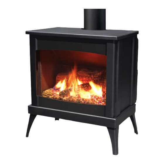
Westport IPI - Steel
F R E E S T A N D I N G G A S F I R E P L A C E
OWNER'S MANUAL
WARNING:
If the information in this manual is not followed exactly, a
fire or explosion may result causing property damage, personal injury
or loss of life. Installation and service must be performed by a qualified
installer, service agency or the gas supplier.
50-3403
Version Française: www.enviro.com/fr.html
Advertisement
Table of Contents

Related Manuals for Enviro Westport IPI Steel


Summary of Contents for Enviro Westport IPI Steel
- Page 1 If the information in this manual is not followed exactly, a fire or explosion may result causing property damage, personal injury or loss of life. Installation and service must be performed by a qualified installer, service agency or the gas supplier. 50-3403 Version Française: www.enviro.com/fr.html...
-
Page 2: Safety Precautions
Safety Precautions WARNING: FIRE OR EXPLOSION HAZARD Failure to follow safety warnings exactly could result in serious injury, death, or property damage. - Do not store or use gasoline or other flammable vapors and liquids in the vicinity of this or any other appliance. - WHAT TO DO IF YOU SMELL GAS •... - Page 3 Safety Precautions FOR SAFE INSTALLATION AND OPERATION OF YOUR “ENVIRO” HEATER, PLEASE CAREFULLY READ THE FOLLOWING INFORMATION: • All ENVIRO gas-fired appliances must be installed in • A barrier designed to reduce the risk of burns from the accordance with their instructions. Carefully read all the hot veiwing glass is provided with this appliance and shall instructions in this manual first.
-
Page 4: Table Of Contents
Table of Contents Safety Precautions .............................2 Table of Contents ............................4 Codes And Approvals ..........................5 Specifications ............................6 Dimensions: ..........................6 Rating Label & Lighting Instructions Location: .................6 Operating Instructions ..........................7 Lighting Instructions: ........................7 Air Shutter (Venturi): ........................8 Normal Sounds During Operation: ....................9 Remote Control Operations: ......................10 System Description: ........................10 Technical Data: ...........................10... -
Page 5: Codes And Approvals
After the unit has gone through the first burn, turn the unit off including the pilot, let the unit get cold then remove the glass door and clean it with a good gas fireplace glass cleaner, available at your local ENVIRO dealer. -
Page 6: Specifications
Specifications WARNING: Operation of this heater when not connected to a properly installed and maintained venting system can result in carbon monoxide (CO) poisoning and possible death. imensions 24 1 " 61.3cm 27 1 " 70cm 16" 40.7cm 19 1 "... -
Page 7: Operating Instructions
Operating Instructions For Your Safety, Read Safety Precautions And Lighting Instructions Before Operating WARNING: IF YOU DO NOT FOLLOW THESE INSTRUCTIONS EXACTLY A FIRE OR EXPLOSION MAY RESULT, CAUSING PROPERTY DAMAGE, PERSONAL INJURY OF LOSS OF LIFE. iLot ighting nstRuctions FOR YOUR SAFETY READ BEFORE OPERATING WARNING: IF YOU DO NOT FOLLOW THESE INSTRUCTIONS EXACTLY, A FIRE OR EXPLOSION... - Page 8 Operating Instructions hutteR The air shutter is controlled with the primary air adjustment rod located behind the gas valve shown in Figure 4. The air shutter allows the amount of air coming into the fireplace to be adjusted in order to accommodate different climates and venting arrangements.
- Page 9 After the unit has gone through the first burn, turn the unit OFF, including the pilot, and let the unit completely cool. Then remove the glass and clean it with a good gas fireplace glass cleaner, available at your local Enviro dealer. See M aIntenance...
-
Page 10: Remote Control Operations
Operating Instructions emote ontRoL PeRations Proflame 2 is a modular remote control system that directs the functions of the Westport. The Proflame 2 TMFSLA is configured to control the on/off main burner operation, its flame levels and provides on/off and Smart thermostatic control of the appliance. The system also controls the fan speed through six (6) levels. - Page 11 Operating Instructions Key Lock Transmission Low battery alarm Thermostat OFF/ Room ON/SMART Temperature CPI mode Set Point Aux ON Temperature/Level/State Flame ON Split Flow Dimmer ON Comfort fan Figure 6: Proflame 2 Transmitter LCD Screen. (iFc): ntegRateD iRePLace ontRoLLeR The Proflame 2 IFC (Figure 7) connects directly to the gas valve, split flow valve, stepper motor, pilot and covection fan with a wiring harness.
-
Page 12: Operating Procedure
Operating Instructions PeRating RoceDuRe Initializing The System For The First Time Install the four (4) AA batteries into the IFC battery holder. Note the polarity of the battery and insert into the battery bay as indicated on the body of the battery holder. Press the reset button on the IFC marked “SW1” (see Figure 7). The IFC will “beep”... - Page 13 Operating Instructions Turn off the Appliance Room Temperature Press the ON/OFF Key on the Transmitter. The Transmitter LCD display will only show the room temperature and Icon (see Figure 10). A single “beep” from the IFC confirms reception of the command and both the pilot light (if the unit is not set to continuous pilot) and main burner will turn off.
- Page 14 Operating Instructions Auxiliary Control This function is not used on the Westport and can be disregarded. Figure 14: Auxiliary Control (not used) Dimmer Control This function is not used on the Westport and can be disregarded. Figure 15: Dimmer Control Key lock This function will lock the keys to avoid unsupervised operation.
-
Page 15: Maintenance And Service
Do not operate with the glass front removed, cracked or broken. Removal and replacement of the glass from the door must be done by a licensed or qualified service person. The glass must be purchased from an ENVIRO dealer. No substitute materials are allowed. -
Page 16: Burner Removal
Maintenance And Service Lass ooR anD ascia emovaL Turn unit off and wait until the appliance has cooled down. Remove the stovetop from the unit by lifting straight up. Lift the two door handles located on either side of the door and lift the glass door assembly straight up and out (see Figure 6 and 7). -
Page 17: Fuel Conversion
Maintenance And Service onveRsion TO BE INSTALLED BY A QUALIFIED SERVICE AGENCY ONLY Please read and understand these instructions before installing. Warning: This conversion kit shall be installed by a qualified service agency in accordance with the manufacturer’s instructions and all applicable codes and requirements of the authority having jurisdiction. - Page 18 Maintenance And Service onveRsion 6. Convert the burner orifice: a) Remove the main burner orifice with a 1/2” socket b) Put a bead of pipe-thread sealant into the orifice mount. DO NOT OVER-TIGHTEN c) Install the new orifice: 7. Convert the SIT gas valve: a) Use a T-20 driver to remove the two screws that hold the servo regulator to the gas valve and disconnect the wire harness from the IFC.
-
Page 19: Initial Installation
Initial Installation QUALIFIED INSTALLERS ONLY WARNING: Operation of this heater when not connected to a properly installed and maintained venting system can result in carbon monoxide (CO) poisoning and possible death. RePaRation nstaLLation • Remove the packaging from the appliance, and check to make sure there is no damage. If damage is found, please report it to both the carrier and your dealer as soon as possible. - Page 20 Initial Installation QUALIFIED INSTALLERS ONLY LeaRances to ombustibLes A. Sidewall to unit 11 inches (27.9 cm) B. Backwall to unit 2.5 inches (6.35 cm) Adjacent wall C. Corner to unit 2.5 inches (6.35 cm) Back wall D. Ceiling 60 inches above floor (152.4 cm) E.
- Page 21 Initial Installation QUALIFIED INSTALLERS ONLY Round Support Your total vent pipe length must be within the Box/Wall Thimble shaded area of Figure 23. If a 90° elbow is used in the horizontal plane, 36” (91.4 cm) must be subtracted from the allowable horizontal run. There are three (3) basic types of Direct Vent Horizontal System installations.
-
Page 22: Vent Termination Restrictions
Initial Installation QUALIFIED INSTALLERS ONLY eRmination estRictions Fixed Closed Fixed Openable Closed Openable Termination Cap Air Supply Inlet Gas Meter Restriction Zone (Termination not allowed) Figure 19. Vent Termination Restrictions, refer to Table 3. Table 3: Vent termination clearances, refer to Figure 18. Letter Canadian Installation US Installation... - Page 23 Initial Installation QUALIFIED INSTALLERS ONLY 50-1235: iRePLace oRizontaL Please read and understand these instructions before installing. Failure to follow these instructions carefully could cause property damage or personal injury. KIT COMPONENTS: Qnty Description Qnty Description Horizontal direct vent termination cap Wire spacers Flue collar adapter 4 oz tube Mill-Pac Sealant...
- Page 24 Initial Installation QUALIFIED INSTALLERS ONLY 10. Apply a bead of Mill-Pac Black sealant to the top section of the Ø4” (10 cm) by 5” Horizontal Vent Termination (12.5 cm) flue collar adaptor previously installed into the fireplace flue outlet. Slide the Ø4” (10 cm) flex vent over the flue collar and secure with three (3) sheet metal screws evenly spaced.
- Page 25 Initial Installation QUALIFIED INSTALLERS ONLY EXCEPTION TO WARNING: This product has been evaluated by Intertek for using a Direct Vent GS starting collar in conjunction with Secure Vent, Direct-Temp, and Ameri Vent Direct venting systems. Use of these systems with the Direct Vent GS starting collar is deemed acceptable and does not affect the Intertek WH listing of the appliance.
- Page 26 Using 45˚ elbows is preferable to using 90˚ elbows. Also, a shorter vent system will perform better than a longer one. The ENVIRO WESTPORT has been designed with a built in restrictor plate. The restrictor is designed to enhance flame appearance when...
- Page 27 Initial Installation QUALIFIED INSTALLERS ONLY oRizontaL nstaLLation 1. Set the appliance in the desired location. Check to determine if wall studs or roof rafters are in the way when the venting system is attached. If this is the case, you may want to adjust the location of the appliance.
- Page 28 Initial Installation QUALIFIED INSTALLERS ONLY wall, run a bead of non-hardening mastic around the edges, so as to make a seal between the termination and the wall. The arrow on the vent termination should be pointing up, insure that the proper clearances to combustible materials are maintained.
- Page 29 Initial Installation QUALIFIED INSTALLERS ONLY eRticaL nstaLLation 1. Check the instructions for required clearances (air spaces) to combustibles when passing through ceilings, walls, roofs, enclosures, attic rafters, or other nearby combustible surfaces. Do not pack air spaces with insulation. 2. Set the gas appliance in the desired location. Drop a plumb bob down from the ceiling to the position of the appliance flue exit, and mark the location where the vent will penetrate the ceiling.
- Page 30 Initial Installation QUALIFIED INSTALLERS ONLY the support straps that extend out beyond the edge of the flashing. 7. Slip the flashing over the pipe section protruding through the roof. Secure the base of the flashing to the roof with roofing nails. Use a non-hardening sealant between the uphill edge of the flashing and the roof.
- Page 31 Initial Installation QUALIFIED INSTALLERS ONLY Nails Ceiling firestop plumber’s tape connected to wall strap Ceiling Wall strap Use clearances to as defined by appliance and vent pipe manufacturers. 45° elbows (x2) Second floor Figure 34: Multi-Story Vent Pipe Installation. Figure 33: Use of Wall Straps. atheDRaL eiLing nstaLLation...
- Page 32 Initial Installation QUALIFIED INSTALLERS ONLY 5. Using tin snips, cut the “Support Box” from the top corners down to the roof line, and fold the resulting flaps over the roof sheathing (Figure 36). Before nailing it in to the roof, run a bead of non-hardening mastic around the top edges of the “Support Box”, to make a seal between the box and the roof.
- Page 33 Initial Installation QUALIFIED INSTALLERS ONLY onveRting enteD into enteD This unit has been shipped as a 30,000 Btu/hr top-vented freestanding unit. This unit can be converted to a rear vented unit with a 36” (915 mm) snorkel for some installation applications.To convert this unit to a rear vented model you must remove the flue pipe adapter and turn to the rear vent position.
- Page 34 Initial Installation QUALIFIED INSTALLERS ONLY Firebox Top Flue Collar Adapter Undo four ¼" screws that hold flue collar elbow to unit. Figure 41: Step 4 of Converting Top Figure 40: Step 3 of Converting Top Vented into Vented into Rear Vented. Rear Vented.
-
Page 35: Corner Installation
Initial Installation QUALIFIED INSTALLERS ONLY nstaLLation oF enteD oRizontaL eRmination This is the most common type of installation style. Set the unit in place. Termination Install a minimum 24” (61 cm) vertical chimney. Inside finished collar Install a 90° elbow, and mark the exterior wall where the vent would pass through. - Page 36 Initial Installation QUALIFIED INSTALLERS ONLY - 50-841: ReestanDing RaFthooD DaPtoR This Drafthood Adaptor is a complete assembly and is ready to fit onto your Westport in a vertical vent application only. With the Drafthood Adaptor correctly installed and wired to the gas control valve. Your Direct Vent Fireplace can be vented like a B-Vent Fireplace.
- Page 37 Initial Installation The minimum clearance to combustibles is 6” (150 mm) when using single wall venting and 1” (25 mm) when using “B-vent” venting. We strongly recommend installing an approved chimney liner in an existing brick chimney. This will maximize the potential draft of the chimney and lessen the effects of slow chimney start-up. VENTING OF A FIREPLACE FITTED WITH THE DRAFTHOOD ADAPTOR: Note: Please refer to the chimney manufacturer’s installation instructions prior to commencing the installation.
- Page 38 Initial Installation AUTOMATIC SAFETY SHUT DOWN: If the spill switch is activated and shuts off the main burner the following procedure should be followed. • Is the pilot flame still on? If not, the reason for the fireplace shut down is not the spill switch. •...
- Page 39 Initial Installation QUALIFIED INSTALLERS ONLY onnection anD esting WARNING: Only persons licensed to work with gas piping may make the necessary gas connections to this appliance. GAS LINE CONNECTION Manifold Pressure Tap • This stove is equipped with a certified flexible pipe Servo located on the right side of the unit terminating in a ⅜”...
-
Page 40: Electrical Requirements
Initial Installation QUALIFIED INSTALLERS ONLY LectRicaL equiRements The fireplace must be electrically connected and grounded in accordance with local codes or, in the absence of local codes, with the current CSA C22.1 Canadian Electrical Code Part 1, Safety Standards For Electrical Installations, or The National Electrical Code ANSI / NFPA 70 in the US. -
Page 41: Secondary Installation
Placement Pin for Left Rear Log If over time, through cleaning and servicing, these embers require replacement, contact the nearest ENVIRO dealer for replacement embers. Note: Log set shown with optional panel set (50-1038) installed. Figure 55: Step 2 of Log Placement. - Page 42 Secondary Installation 1. Carefully remove logs from box. Check to ensure there is Ledge for no damage. It is very important Center Log to install all logs in their proper position to insure safe, optimum Placement Pin operating conditions. for Center Log 2.
- Page 43 Figure 59: Log Placement with Rock Wool. cold then remove the glass door and clean it with a good gas fireplace glass cleaner, available at your local ENVIRO dealer. See M on how to remove aIntenance ervIce door to clean glass.
- Page 44 Secondary Installation (50-1038): nstaLLation oF PtionaL aneL Do not install when the unit is hot. The brick panel set is fragile. Handle panels with care and avoid knocking them on the placement pins or any other object. 1. Remove the two (2) screws from the rear of the baffle, use a ¼”...
- Page 45 Secondary Installation emovaL oF aFety cReen The safety screen supplied with the Westport comes installed on the back of the front fascia and must be used whenever the stove is on or cooling down. If necessary, the safety screen can be removed for cleaning or replacement by following the steps below.
-
Page 46: Trouble Shooting
Trouble Shooting Problem Possible Cause Solution The main burner does not The gas valve may not be on. • Check that the gas control knob is in the “ON” position. ignite when called for. Thermostat is not calling for • Adjust the thermostat several degrees above ambient heat. -
Page 47: Parts List
Parts List - Components Reference Part Description Part Number Number Cover Plate 50-3397 Valve Mounting Bracket 50-3398 Complete Valve Assembly 50-3401 Proflame 2 IFC (0.584.326) 50-3202 Proflame 2 Wire Harness (0.584.902) 50-3030 Blank Orifice #73 - All Gas Models 50-343 Inner Door Handles (2 per set) 30-052 Inner Door Only - Painted... - Page 48 Parts List - Components Firebox 30-054 Firebox Baffle 50-533 Domestic Power Cord EC-042 HEYCO Strain Relief EC-044 Battery Holder 4 x AA 50-3027 Embers 50-491 4” Flex Coupler 50-497 Westport Replacement Safety Screen 50-3060 Owner’s Manual 50-3403 Brick Panel Set 50-1038 Log Set With Embers - Complete 50-1041...
- Page 49 Parts Diagram - Components DATE: 11/04/2017 SHERWOOD INDUSTRIES LTD. BY -- UPDATED: ----/--/-- INTERNAL ASSEMBLY MANUAL SHEET: STOVE: REVISION:...
- Page 50 Notes...
- Page 51 Sherwood Industries Ltd. (“Sherwood”) hereby warrants, subject to the terms and conditions herein set forth, this product against defects in material and workmanship An expanded list of exclusions is available at www.enviro.com/help/warranty.html during the specified warranty period starting from the date of original purchase at retail.
-
Page 52: Installation Data Sheet
� NATURAL GAS (NAT) PROPANE(LPG) _________________________________________ INLET GAS PRESSURE:_________in wc PHONE:___________________________________ MAIN BURNER ORIFICE:__________# DMS PILOT ORIFICE #_________OR________in diam. INSTALLER’S SIGNATURE: _________________________________________ MANUFACTURED BY: SHERWOOD INDUSTRIES LTD. 6782 OLDFIELD RD. SAANICHTON, BC, CANADA V8M 2A3 www.enviro.com April 10, 2017 C-15144...
Need help?
Do you have a question about the Westport IPI Steel and is the answer not in the manual?
Questions and answers