Table of Contents
Advertisement
Quick Links
One Technology Way • P.O. Box 9106 • Norwood, MA 02062-9106, U.S.A. • Tel: 781.329.4700 • Fax: 781.461.3113 • www.analog.com
FEATURES
Input voltage: 2.7 V to 5.0 V
Evaluates single LED flash driver performance
I
2
C interface
Jumpers for measurement of flash LED current and supply
current
Evaluation software CD with measurement report included
GENERAL DESCRIPTION
The evaluation system is composed of a motherboard, daughter-
board, and LED subboard. The motherboard provides the I
signals from the PC USB port and generates the I/O voltages
and digital high and low signals for the daughterboard. For
overtemperature measurement, the daughterboard can be either
plugged directly into the motherboard or connected to the
motherboard via a ribbon cable.
PLEASE SEE THE LAST PAGE FOR AN IMPORTANT
WARNING AND LEGAL TERMS AND CONDITIONS.
ADP1650 Evaluation Board
The motherboard features a 3.3 V regulator and 2.8 V/1.8 V
regulators for VDDIO. The daughterboard contains jumpers
and test points for easy evaluation of the flash driver integrated
circuit (IC).
Operating details are provided in the
which should be consulted in conjunction with this evaluation
board user guide.
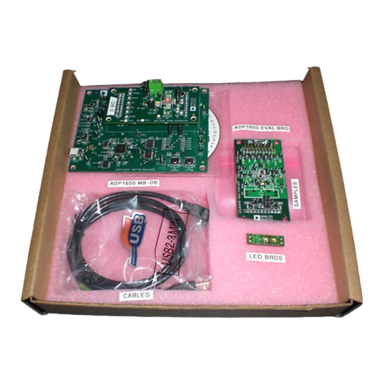
Figure 1 shows the contents of the ADP1650-EVALZ kit, which
includes
•
2
C
•
•
The ADP1650-EVALZ is intended for very detailed evaluation.
Contact a local sales office at Analog Devices, Inc., to request it.
ADP1650 EVALUATION BOARD KIT
Figure 1.
Rev. A | Page 1 of 16
Evaluation Board User Guide
Cables: power (red/black), USB, 2× current measurements
Samples: five ADP1650 devices, two FDSD3012 inductors
LED boards: OSRAM LUWF65N, LumiLEDs PWF-4
UG-139
ADP1650
data sheet,
Advertisement
Table of Contents

Subscribe to Our Youtube Channel
Related Manuals for Analog Devices ADP1650


Summary of Contents for Analog Devices ADP1650
-
Page 1: Features
The ADP1650-EVALZ is intended for very detailed evaluation. plugged directly into the motherboard or connected to the Contact a local sales office at Analog Devices, Inc., to request it. motherboard via a ribbon cable. ADP1650 EVALUATION BOARD KIT Figure 1. -
Page 2: Table Of Contents
REVISION HISTORY 9/10—Rev. 0 to Rev. A Added Installing the LabVIEW Run-Time Engine Section ..3 Changes to Installing ADP1650 Evaluation Software Section ... 3 Changes to Using the Software GUI Section ........ 5 Deleted ADC Mode Section ............7 Deleted ADP1650 EVALZ for Detailed Evaluation Section .. -
Page 3: Evaluation Board Software
INSTALLING THE LABVIEW RUN-TIME ENGINE The LabVIEW™ run-time engine must be installed on the PC first unless LabVIEW 2009 is already installed. Insert the ADP1650-EVALZ setup CD into the CD-ROM and run LVRTE90STD.exe. INSTALLING ADP1650 EVALUATION SOFTWARE Insert the ADP1650-EVALZ setup CD into the CD-ROM and run Setup.exe. -
Page 4: Usb Driver Installation
USB DRIVER INSTALLATION Click Continue Anyway and then Finish to complete the driver installation. Plug the ADP1650 board into the computer using the USB cable provided with the evaluation kit. When the system recognizes the board, the Found New Hardware Wizard dialog box appears. -
Page 5: Using The Software Gui
Ensure that the daughterboard is supplied with a source HARDWARE CONFIGURATION AND MONITORS that can supply 3 A. Complete the following steps to load the ADP1650 evaluation Click the Start button at the bottom left on your desktop. software: Select All Programs, then the Analog Devices folder, and Before running the software, ensure that the motherboard then ADP1650 Evaluation Software v1.0 to load the... -
Page 6: Led Current Programming
Click the STROBE button in Section 8 of the window to user registers window. initiate flash. Ensure a write to the ADP1650 by clicking the appropriate Program the length of the flash event by setting the value refresh button in Section 6 on the right side of the user under S/W Flash Timer in Section 2 and clicking the registers window. -
Page 7: Deleted Adc Mode Section
Section 7 of the user registers window is used to read back the Set the low VBAT threshold and the desired current setting in fault detection status from the ADP1650. Click Read 0x05 to Section 4 of the user registers window. The battery voltage can view information about the fault. -
Page 8: Evaluation Board Overview
Figure 9. Motherboard The ADP1650 motherboard provides the interface signals to the Typically, the daughterboard is inserted directly into the 20-pin ADP1650 flash driver IC. These signals are controlled via the header of the motherboard. For temperature measurements, evaluation software GUI. -
Page 9: Demo Daughterboard
IR drops. A high current can cause a big IR drop, and V High V LEDs ADP1650 can be low enough to put the part into UVLO. The LED subboard (at U2 in Figure 10) can be replaced with a different subboard containing various LEDs with higher V... -
Page 10: Power Board From Usb Port Only
TORCH AND STROBE: USE PUSH-BUTTONS FOR CY68013 A MICROCONTROLLER: EXTERNAL TORCH OR FLASH. BUTTONS MUST PROVIDES USB-TO-I C CONVERSION BE ENABLED FROM SOFTWARE GUI. Figure 11. Powering the ADP1650 from a USB Port Rev. A | Page 10 of 16... -
Page 11: Deleted Adp1650 Evalz For Detailed Evaluation Section
Evaluation Board User Guide UG-139 EVALUATION BOARD SCHEMATICS Figure 12. ADP1650 Evaluation Motherboard Schematic Rev. A | Page 11 of 16... - Page 12 UG-139 Evaluation Board User Guide Figure 13. ADP1650 Evaluation Daughterboard Schematic Rev. A | Page 12 of 16...
- Page 13 Evaluation Board User Guide UG-139 Figure 14. LED Subboard Rev. A | Page 13 of 16...
-
Page 14: Changes To Bill Of Materials Section
Connector header, 1 pin × 1 Samtec TSW-150-07-T-S TP1, TP10 to TP14, TP21, TP23 to TP28, TP30, TP31 ADP1650, 12-ball WLCSP Analog Devices ADP1650 ADP1650 plug-in LED boards, six pcs gold Kensington YSK0076-011AH sockets Table 2. LED Subboard Bill of Materials Reference Designator Description Manufacturer/Vendor... - Page 15 Connector header Sullins Electronics PEC36SAAN IC MCU USB peripheral high speed 56-QFN Cypress CY7C68013A-56LFXC Semiconductor ADP3303, 3.3 V Analog Devices ADP3303-3.3 IC SRL EEPROM I2C, 64 kB, SO-8 STMicroelectronics M24C64 IC 10-bit voltage clamp, 24-TSSOP NXP Semiconductors GTL2010PW ADG734BRUZ, 20-lead TSSOP...
- Page 16 By using the evaluation board discussed herein (together with any tools, components documentation or support materials, the “Evaluation Board”), you are agreeing to be bound by the terms and conditions set forth below (“Agreement”) unless you have purchased the Evaluation Board, in which case the Analog Devices Standard Terms and Conditions of Sale shall govern. Do not use the Evaluation Board until you have read and agreed to the Agreement.
Need help?
Do you have a question about the ADP1650 and is the answer not in the manual?
Questions and answers