
Related Manuals for Wilo DrainLift SANI-XL


Summary of Contents for Wilo DrainLift SANI-XL
- Page 1 Pioneering for You Wilo-DrainLift SANI-XL en Installation and operating instructions · 2552855 • Ed.03/2023-06...
- Page 2 DrainLift SANI-XL https://qr.wilo.com/483...
-
Page 3: Table Of Contents
Staff qualifications.............. 14 Installation types.............. 14 Operator responsibilities............ 14 Installation ................ 14 Electrical connection ............ 20 7 Commissioning ................. 22 Staff qualifications.............. 22 Operator responsibilities............ 22 Operation ................ 23 Test run ................ 23 Follow-up time.............. 23 Setting the venting screw.......... 24 8 Operation .................. 24 Installation and operating instructions • Wilo-DrainLift SANI-XL • Ed.03/2023-06... -
Page 4: About These Instructions
All rights reserved. Subject to change Wilo reserves the right to change the listed data without prior notice and is not liable for technical inaccuracies and/or omissions. The illustrations vary from the original and are in- tended as a sample representation of the device. - Page 5 Danger due to bacterial infection Warning – risk due to hot surfaces Wear protective helmet. Wear safety shoes. Wear safety gloves. Wear respiratory mask. Wear safety glasses. Be aware about the instructions. Useful information Installation and operating instructions • Wilo-DrainLift SANI-XL • Ed.03/2023-06...
-
Page 6: Electrical Work
The mentioned branded articles are non-binding suggestions. Similar products from other brands can also be used. The pre- requisite is the fulfilment of the mentioned standards. WILO SE accepts no liability for the mentioned articles regarding their conformity to the relevant standards. Electrical work •... -
Page 7: Monitoring Devices
Only use undamaged tanks (no cracks, leaks, porous material). Switch off lifting units with damaged tanks immediately. • Ensure that all connections for the inlet, discharge pipe, and ventilation are sealed tightly and executed according to the local regulations. Installation and operating instructions • Wilo-DrainLift SANI-XL • Ed.03/2023-06... -
Page 8: Transport
Open all shut-off valves in the inlet and discharge pipe. • The maximum inflow must be lower than the maximum output of the system. • Do not open the inspection opening. • Ensure the operating space is well ventilated. Installation and operating instructions • Wilo-DrainLift SANI-XL • Ed.03/2023-06... -
Page 9: 2.11 Cleaning And Disinfection
• For backflow resistant drainage in cases where the discharge point is below the back- flow level NOTICE! Install grease traps upstream of the lifting unit if pumping greasy sewage! Installation and operating instructions • Wilo-DrainLift SANI-XL • Ed.03/2023-06... -
Page 10: Improper Use
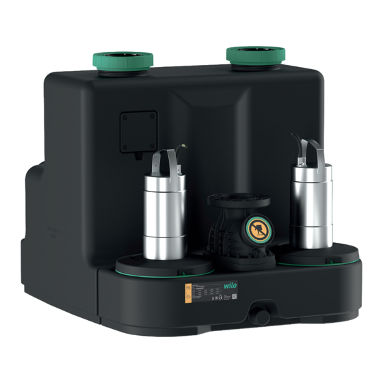
Surface-cooled (air) or self-cooling (sheath flow cooling) motor with thermal motor monit- oring. Fig. 1: Overview Pre-installed switchgears for automatic operation: Wilo-Control MS-L • Collective fault signal with potential-free contact • Integrated and mains-independent alarm • Adjustable follow-up time Installation and operating instructions • Wilo-DrainLift SANI-XL • Ed.03/2023-06... -
Page 11: Materials
4 = operating mode: S1, switchgear: Control EC-L Version for aggressive fluids Technical data Approved field of application Max. pressure in the discharge pipe 6 bar (87 psi) Max. delivery head See rating plate Max. volume flow See rating plate Installation and operating instructions • Wilo-DrainLift SANI-XL • Ed.03/2023-06... -
Page 12: Manufacturer Date
S3! DrainLift SANI-XL.../4...: The unit is designed for continuous duty! The max. volume flow applies to continuous duty S1! Manufacturer date The manufacture date is indicated according to ISO 8601: YYYYWww Installation and operating instructions • Wilo-DrainLift SANI-XL • Ed.03/2023-06... -
Page 13: Scope Of Delivery
Newly supplied lifting units can be stored for one year. For longer storage periods, contact customer service. When storing the pump, please note the following points: • Place the lifting unit securely on a firm surface and secure it against slipping and falling over. Installation and operating instructions • Wilo-DrainLift SANI-XL • Ed.03/2023-06... -
Page 14: Installation And Electrical Connection
Always transport the lifting unit and align it at the installation location with two persons. Building installation • Ensure the operating space is well ventilated. Installation and operating instructions • Wilo-DrainLift SANI-XL • Ed.03/2023-06... - Page 15 In order to ensure safe and proper operation, the piping and pipe connections must be checked based on the following parameters and designed ac- cording to the requirements: Installation and operating instructions • Wilo-DrainLift SANI-XL • Ed.03/2023-06...
- Page 16 Fasten the switchgear to the wall to protect the switchgear from flooding (see switchgear instructions). Lay the connection cable according to regulations. ▶ Lifting unit installed to protect it against buoyancy and twisting. Next step: Connect the discharge pipe. Installation and operating instructions • Wilo-DrainLift SANI-XL • Ed.03/2023-06...
- Page 17 Discharge pipe connected. Next step: Connect the inlet. 6.4.7 Connecting the inlet The inlet can be located in the areas indicated on the rear wall, both side walls and the tank roof, as desired. Installation and operating instructions • Wilo-DrainLift SANI-XL • Ed.03/2023-06...
- Page 18 Fig. 5: Connect the inlet Tank wall Hole saw for drill Inlet seal Inlet pipe Pipe clamp ✓ Lifting unit installed properly. ✓ Inlet pipe installed to the collection tank according to the consulting documents. Installation and operating instructions • Wilo-DrainLift SANI-XL • Ed.03/2023-06...
- Page 19 Insert the ventilation pipe into the HT double socket. ▶ Ventilation pipe installed. If required, connect a diaphragm hand pump to the con- nection for emergency drainage. Fig. 6: Collection tank ventilation connection Installation and operating instructions • Wilo-DrainLift SANI-XL • Ed.03/2023-06...
-
Page 20: Electrical Connection
20 A Three-phase current SANI-XL12T... 5.8 A 10 A SANI-XL16T... 7.2 A 10 A SANI-XL21T... 11 A 16 A Residual-current device (RCD) • Install a residual-current device (RCD) according to the regulations of the local energy supply company. Installation and operating instructions • Wilo-DrainLift SANI-XL • Ed.03/2023-06... - Page 21 NOTICE! If the inlet is lower than the “Pump ON” switching point, there is backflow in the inlet pipe! Wilo-Control MS-L switchgear The switching points are set via permanently defined parameter sets for the Wilo-Con- trol MS-L switchgear. Set the required parameter set to DIP switch 3: Switching points Pump ON: 250 mm (10 in)
-
Page 22: Commissioning
Wilo-Control EC-L switchgear The switching points are set via the menu for the Wilo-Control EC-L switchgear. Set the following values in the specified menus: Switching points Pump 1 ON: 250 mm (10 in) • 1.00 0.50 0.11 0.53 0.16 0.55 Pump 2 ON: 260 mm (10.2 in) Pump 1 OFF: 115 mm (4.5 in) -
Page 23: Operation
To set the follow-up time, read the installation and operating instructions for the switchgear. CAUTION! Pay attention to the operating mode if the follow-up time is changed! The operating mode indicates the duty period and the standby time! Installation and operating instructions • Wilo-DrainLift SANI-XL • Ed.03/2023-06... -
Page 24: Setting The Venting Screw
• Increase the follow-up time to prevent the pressure surges. • An extended follow-up time results in slurping operation and smoother closing of non-return valve. Installation and operating instructions • Wilo-DrainLift SANI-XL • Ed.03/2023-06... - Page 25 • Installation and dismantling to be performed by a trained expert for sanitary installa- tions, including fastening of buoyancy safeguard and connection of plastic pipes. Installation and operating instructions • Wilo-DrainLift SANI-XL • Ed.03/2023-06...
- Page 26 Performing work in chambers and narrow rooms as well as in areas with risk of falling can be dangerous. Do not perform this work alone! • Only perform the work with another person! Installation and operating instructions • Wilo-DrainLift SANI-XL • Ed.03/2023-06...
- Page 27 Close the inspection opening on the collection tank and non-return valve again. Maintenance and repair Maintenance and repair work can only be carried out by qualified staff (e.g. customer ser- vice). The maintenance intervals in accordance with EN 12056‑4: Installation and operating instructions • Wilo-DrainLift SANI-XL • Ed.03/2023-06...
- Page 28 • Observe the locally applicable regulations. Consult your local municipality, the nearest waste disposal site, or your retailer for informa- tion on proper disposal. See www.wilo‑recycling.com for more information about recycling. Installation and operating instructions • Wilo-DrainLift SANI-XL • Ed.03/2023-06...
- Page 32 Local contact at www.wilo.com/contact WILO SE Wilopark 1 44263 Dortmund Germany T +49 (0)231 4102-0 T +49 (0)231 4102-7363 wilo@wilo.com Pioneering for You www.wilo.com...
Need help?
Do you have a question about the DrainLift SANI-XL and is the answer not in the manual?
Questions and answers