Table of Contents
Advertisement
Quick Links
Advertisement
Table of Contents

Related Manuals for Knauer Azura SMB Lab


Summary of Contents for Knauer Azura SMB Lab
- Page 1 SMB systems Instructions Document no. V6775...
- Page 2 KNAUER. Support: Do you have questions about the installation or the operation of your instrument or software? International Support: Contact your local KNAUER partner for support: www.knauer.net/en/Support/Distributors-worldwide Support in Germany (Austria & Switzerland on case-to-case basis): Phone:...
-
Page 3: Table Of Contents
Table of contents 1. Product information..............1 Intended use . - Page 4 Table of contents 5. Unpacking and setup............. . . 14 Operating environment.
- Page 5 Table of contents SOP: AZURA® SMB separation ..........44 8.4.1 Preparation .
- Page 6 Table of contents 14. Chemical compatibility of wetted materials ......... . . 65 14.1 General .
-
Page 7: Product Information
1. Product information Intended use Note: Only use the system for applications that fall within the range of the intended use. Otherwise, the protective and safety equipment of the system could fail. Application Separation and extraction Pharmaceutical Chiral compound (cis-trans phytol, chemistry steroids, peptides, antibiotics, etc.) Food chemistry... -
Page 8: Azura® Smb Pilot
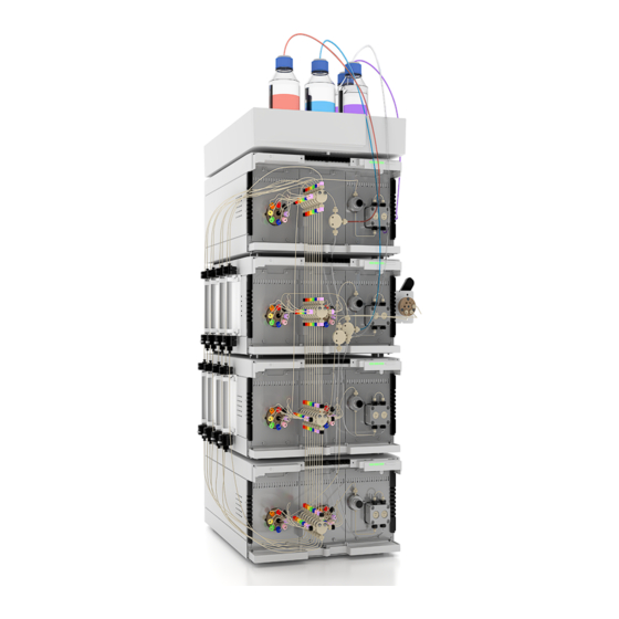
Product information Fig. 1: System layout AZURA® SMB Lab (example) 1.2.2 AZURA® SMB Pilot The AZURA® SMB Pilot is designed for the separation of binary mixtures on a hundred gram to kilogram scale and is typically used with columns up to 50 or 100 mm ID. -
Page 9: System Configuration
Product information Fig. 2: System layout AZURA® SMB Pilot (example) System configuration The standard AZURA® SMB systems consists of four pumps and seven multi- position valves. The devices are arranged as follows: Three pumps (Extract, Raffinate, Eluent) are placed inside the SMB cycle. ƒ... -
Page 10: Azura® Smb Lab
Product information Fig. 3: SMB design scheme 1.3.1 AZURA® SMB Lab Max. continuous Number of Pressure range Art. No. Description flow rate* columns 30 ml/min 10 - 130 bar A29100 Biocompatible (PAEK, ceramic) 30 ml/min 10 - 130 bar A29101 Stainless steel * The maximum operating parameters for flow and pressure depend on the specific columns and customer aplication. -
Page 11: Scope Of Delivery
2. Scope of delivery Note: Only use original parts and accessories made by KNAUER or a com- pany authorized by KNAUER. AZURA® SMB Lab System 1 x AZURA® Assistant ASM 2.2L with 1 x AZURA® Pump P 4.1S ƒ (10 ml pump head) and 1 x 8-Multiposition-valve 3 x AZURA®... -
Page 12: Azura® Smb Pilot System
Scope of delivery AZURA® SMB Pilot System 1 x AZURA® Assistant ASM 2.2L with 1 x 8-Multiposition-valve ƒ 3 x AZURA® Assistant ASM 2.2L with 2 x 8-Multiposition-valves ƒ 1 x BlueShadow pump 80P (100 ml pump head) ƒ 3 x BlueShadow pump 80P (500 ml pump head) ƒ... -
Page 13: General
These operating instructions are an integral part of the device. It has to be kept in the immediate vicinity of the device and accessible to the user at all times. You can download these and other instructions from the KNAUER website: www.knauer.net/library Signal words Possible dangers related to the device are distinguished in personal and material damages. -
Page 14: Legal Information
3.4.4 Warranty seal A blue or orange warranty seal is affixed to some devices. A blue seal is used by KNAUER’s Manufacturing or Customer Support for ƒ devices to be sold. After repair, service technicians attach an orange seal onto the identical ƒ... -
Page 15: Basic Safety Instructions
Operation in potentially explosive areas without special and additional ƒ explosion protection. Contact the KNAUER Customer Support for more information. User qualification The users are qualified to handle the device if all of the following points apply: They have at least a basic knowledge of liquid chromatography. -
Page 16: Operator Responsibility
Basic safety instructions Operator responsibility The operator is any person who operates the device himself or leaves it to a third party for use and who bears the legal product responsibility for the protection of the user or third parties during operation. The obligations of the operator are listed below: Know and follow the applicable work safety regulations ƒ... -
Page 17: Working With Solvents
Basic safety instructions Working with solvents 4.6.1 General requirements The user is trained for handling different solvents. ƒ Note recommended solvents and concentrations in these instructions in ƒ order to avoid personal injury or damage to the device. For example, cer- tain chemicals may cause PEEK capillaries to swell or burst (see chapter „14. -
Page 18: Explosive Environment
Devices which are shipped without the completed document “Service re- quest form and decontamination report” will not be repaired. If you would like to return a device to KNAUER, make sure to enclose the completed document: www.knauer.net/servicerequest AZURA® SMB system instructions V6775... -
Page 19: Symbols And Signs
Basic safety instructions 4.10 Symbols and signs The following symbols and signs can be found on the device: Symbol Meaning High-voltage hazard Electrostatic discharge hazard, damages to system, device, or components can occur. Obey maximum load for leak tray during transpor- tation, installation and operation. -
Page 20: Unpacking And Setup
5. Unpacking and setup The HPLC system will be set up, installed and commissioned by KNAUER or a company authorized and contracted by KNAUER. Note: KNAUER recommends inviting future users to be present while setting up and commissioning the module so that they can become familiar with the analyzer and how to handle it. -
Page 21: Storing Unopened Shipping Boxes
Unpacking and setup Fig. 4: Bores holes in the side panel Storing unopened shipping boxes In your planning, include following information for immediate storage. Sufficient space ƒ Storage temperatures has to be in the temperature range 4 – 40 °C, ƒ 39 –... -
Page 22: Power Supply
Electronic defect Electronic hazard when using an identically constructed power adapter from another manufacturer. Only use spare parts and accessories from KNAUER or a company authorized by KNAUER. Power plug The device is intended for use with AC power networks of 100 – 240 V. -
Page 23: Flow Charts
Unpacking and setup Flow charts Fig. 5: Flow chart for AZURA® Lab system Fig. 6: Flow chart for AZURA® Pilot system AZURA® SMB system instructions V6775... -
Page 24: Connecting System To Computer Via Lan
Unpacking and setup Connecting system to computer via LAN The system can be operated in two ways: Via remote connector ƒ As part of a LAN, via the LAN connector of the router ƒ All connectors for external control are located on the back side of the single devices. -
Page 25: Connecting Devices With Lan
Unpacking and setup Process Procedure 1. In Windows, open <Network and Sharing Center>. 2. Double-click on <LAN connection>. 3. Click on the button <Properties>. 4. Select <Internet Protocol version 4 (TCP/IPv4)>. 5. Click on the button <Properties>. 6. Check the settings in the tab <General>. The correct settings for the DHCP client are: a) Obtain an IP address automatically b) Obtain DNS server address automatically... -
Page 26: Configuring The Switch
14). 5.7.4 Configuring the switch The switch is preset at the factory. Information about address, user name and password is noted in the router manual: www.knauer.net/PC-hardware. Process Procedure 1. To open the switch configuration, start your Internet browser and enter the IP address (does not apply for all switches). -
Page 27: Controlling Several Systems Separately In A Lan
Unpacking and setup 5.7.6 Controlling several systems separately in a LAN Devices connected to a LAN communicate through ports, which are part of the IP address. If more than one chromatography system is connected to the same LAN and you plan on controlling them separately, you can use diffe- rent ports to avoid interference. -
Page 28: Connecting The Pin Header
Unpacking and setup 5.7.8 Connecting the pin header To control one device through another, the pin header is used. To use remote control, you have to connect cables to the pin header. The single ports are used to exchange control signals. Prerequisites The device is switched off. - Page 29 Unpacking and setup Process 1. Insert the depressor tool in an upper small opening at the front of the pin header 2. Insert the cable into the opening underneath the inserted de- pressor tool. 3. Pull out the depressor tool. Check whether the cables are tightly attached.
-
Page 30: Start-Up
ƒ The power plugs are connected. ƒ The network connection to the router is established ƒ The chromatography software has been installed by KNAUER or a ƒ com pany authorized by KNAUER. The capillaries are connected. ƒ SOP: SMB power-up and shut-down 6.2.1... -
Page 31: Shut Down
Start-up Step Task Start the PurityChrom® software with double click on the desk- top icon. If the assistants are NOT connected via Error in/out, follow this procedure to power up the SMB. Step Task Power up the router and wait until the self-test is performed. Power up all instruments and the PC. -
Page 32: Sop: Smb Start-Up
Start-up SOP: SMB start-up Follow this procedure to perform an AZURA® SMB system start-up. Ensure that the eluents are HPLC quality and are filtered by 0.45 µm filter. Prerequisite ƒ Fig. 9: In the main flow scheme, only active lines in start position between column loop and multi-position lines are shown. -
Page 33: Preparation
Start-up 6.3.1 Preparation Fig. 10: Visualization of SMB system with initial valve position in Puritychrom® MCC. Step Task “Loop valve” is in position “Open Loop”. Otherwise the air/con- tamination will be transferred continuously through the SMB. Set the valves (default values): pump “Zone 1 out”... -
Page 34: Flushing The System
Start-up 6.3.2 Flushing the system Note: For flushing the system without column, proceed here. For cleaning the whole system including columns, go to chapter “Flushing all columns“. Step Task For the Zone 1 pump, set the flow rate at 25 % of the pump heads max. -
Page 35: Washing One Single Column
Start-up Step Task Wait until there is a stable flow rate exiting the raffinate line and no more air bubbles are visible in the raffinate outlet. A slow dripping out of the waste line can occur. Note: The flow rate in raffinate should be higher than in extract, otherwise check the valve positions, flow rates, purge valves and external check valves. -
Page 36: Flushing All Columns
Start-up Step Task Set the “Loop valve” in position “Open Loop”. Otherwise the air/contamination will be transferred continuously through the SMB. Set the valves “pump Zone 1 out” and “pump Zone 1 in” to the number of the column you want to clean up. Set every other column to +4 positions in comparison of the “washing column“. -
Page 37: Washing All Columns
Start-up 6.3.5 Washing all columns Note: If you want to wash your columns, run the procedure “Flushing the system” with ten column volumes (whole column volume!). Note: The back pressure caused by the specific columns may be too high with the recommended flow rates in the SOP. Reduce the flow rates for each pump in the same ratios to reach moderate pressure values (~ <... -
Page 38: Simulated Moving Bed Principle
7. Simulated Moving Bed principle Introduction Due to the fast development of new compounds and the more precise knowledge about them, there is an increasing demand for purified pro- ducts. In most cases, chemical syntheses produce a lot of side components. Therefore, different separation steps have to be involved into production processes. - Page 39 Simulated Moving Bed principle The chromatographic column packed with a solid phase (adsorbent) will be permanently penetrated by a fluid phase (eluent) with a well defined inter- stitial velocity. At the time t a well defined amount of the sample mixture is injected into the column.
- Page 40 Simulated Moving Bed principle Fig. 13: Process mode of elution chromatography While migrating through the column, these pulses are broadened, due to axial dispersion and different migration velocities and they are separated in- to the pure components due to different interaction forces to the adsorbent. The time between two pulses i and i+1 have to be chosen in such a case, that the slowest component of pulse i elutes before the fastest component of pulse i+1 or just before they overlap too much, where pulse i is injected...
-
Page 41: True Counter-Current Process
Simulated Moving Bed principle True counter-current process By contacting an up-flowing liquid with a down-flowing solid in a separation column, a true counter-current chromatographic process is realized, called True Moving Bed (TMB). The TMB was first commercialized in the hypersorp- tion process of the Union Oil Company of California in the early 1950th. - Page 42 Simulated Moving Bed principle Since a high purity of component A is required in the raffinate stream, com- ponent B has to be adsorbed in section III in the volume between feed inlet and raffinate outlet. Therefore, the function of zone III is to adsorb compo- nent B or to separate it from A, respectively.
-
Page 43: Simulated Counter-Current Process
Simulated Moving Bed principle Simulated counter-current process The simulated counter-current process (Simulated Moving Bed - SMB) was developed in the early 60th by the Universal Oil Products Company. It was mainly applied to industrial-scale separations, like the xylene separation or the fructose-glucose separation. - Page 44 Simulated Moving Bed principle raffi nate feed ZONE 3 ZONE 2 ZONE 4 ZONE 1 extract eluent Fig. 16: SMB process scheme For SMB applications the large column in Fig. 15 can also be substituted by a number of chromatographic columns. This is sketched for 8 columns in Fig.
-
Page 45: Efficiency And Economic Aspects
Simulated Moving Bed principle Fig. 17: Concentration profiles at extract and raffinate outlet (dashed lines: impurities) In Fig. 17 the concentrations are normalized on the feed concentration of each component. These normalized concentrations are plotted versus the time coordinate. There are typical zigzag profiles, where a triangle symbolizes one switching interval or tact. - Page 46 Simulated Moving Bed principle The modes are suitable for preparative scale processes. These scales can be very different ones: While in petrol-chemistry 100,000 metric tons per annum are produced, in the pharmaceutical industry only a few kilograms are produced. From an industrial point of view only elution chromatography and the SMB process are attractive out of the three modes, due to the diffi- culties connected with the solid movement in TMB.
-
Page 47: Operation
8. Operation Software operation To operate the system with software, you have to establish a connection between the LAN port and a computer. The system can be controlled with Puritychrom® MCC. You find a detailed description on chromatography soft- ware in the corres ponding software instructions (document no. V2650). Meaning of the LEDs There are three LEDs and a switch on the front of the devices. -
Page 48: Connecting The Columns
Operation Color Status Operation Right LED green The device has been switched on. flashes green The device not ready Wait until the device is ready for operation. for operation. blue The device is in Press the standby button to standby. end the standby. - Page 49 Operation Fig. 19: Indicated direction of flow of the AZURA® SMB Lab system AZURA® SMB system instructions V6775...
-
Page 50: Azura® Smb Pilot System
Operation 8.3.2 AZURA® SMB Pilot system Install the columns of the AZURA® SMB Pilot system on the left side of the system. As shown in Fig. 20, the inlet and outlet ports to the columns are la- belled. Because of the additional inline sampling loop, you have to connect the inlet port of column 1 to port 1 of the valve. -
Page 51: Preparation
Operation 8.4.1 Preparation Step Task Procedure Perform a preparative separation to determine the SMB ƒ parameters. Use the same column type as for the SMB process (dimen- ƒ sion and packing material). The columns have to be as similar as possible regarding the ƒ... -
Page 52: Pausing The Separation
Operation 8.4.3 Pausing the separation Step Task Procedure If required, the SMB system can be paused at any time by clicking the pause button ( The time will be paused, and all pumps will stop. The valves do not switch anymore. To restart the separation, click the play button ( Improving the productivity The productivity can be improved using the following methods:... -
Page 53: Stopping The Separation
Operation Contamination of extract in raffinate Contamination due to zone IV: 1. Open the eluent recycling valve and check if there is any contamination of extract in the waste. 2. If there is a contamination, increase the flow rate in zone I. Contamination due to zone II: 1. - Page 54 Operation Step Task Procedure Open the Purity Chrom® MCC setup by clicking Select the SMB Zone Configuration in the tab Communication. Choose between Zone 2:2:2:2, 1:3:3:1 or User defined confi- guration. An individual visualization is loaded automatically for each configuration. Close and save the setup.
-
Page 55: User Defined Configuration
Operation 8.5.2 User defined configuration As mentioned in the previous section, the configuration can also be chan- ged to user defined. In the visualization, a valve position can be assigned to each position. Step Task Procedure Open the visualization by clicking Right-click on the column symbol to select the valve position. -
Page 56: From 2:2:2:2 To 1:1:1:1
Operation 8.5.3 From 2:2:2:2 to 1:1:1:1 This section describes the change of the zone configuration from 2:2:2:2 to 1:1:1:1. Step Task Procedure Install one column on every second position: Column 1 at Position 1 Column 2 at Position 3 Column 3 at Position 5 Column 4 at Position 7 Install a coupling instead of a column at the position 2, 4, 6, 8. -
Page 57: Inline Sampling Valve
Operation Step Task Before making any changes, make a note of the current Adjust Parameter. Calculate the new Adjust Parameter using the following equation: AdjustP . flow rate current pump AdjustP flow rate current Change the Adjust Parameter. Close and safe the setup. Note: If the flow rate does not change after adjusting the Adjust Parame- ters, undo your changes in the setup and check the system. - Page 58 Operation You can switch the manually operated inline sampling loop valve between two positions. By switching the valve, you bring the sample loop into the cycle (Pos. 2) and out of the cycle (Pos. 1) as shown in Fig. 22 and Fig. 23. Fig.
- Page 59 Operation Step Task Collect sample: Start with Pos. 2 „Fill sample loop“. ƒ After collecting the sample, switch back to Pos. 1 ƒ „Pull sample from loop“. Press air through the loop with an empty syringe. ƒ As a result of lthis process, your sample will leak out at ƒ...
-
Page 60: Functionality Tests
The test intervals depend on the usage of the device. Execution The test can be carried out either by the Technical Support of KNAUER or by a provider authorized by KNAUER (for a fee). For further information visit our website:... -
Page 61: Troubleshooting
10. Troubleshooting 10.1 First measures Check all cabling. ƒ Check all screw fittings. ƒ Check whether air has intruded the supply lines. ƒ Check the device for leaks. ƒ Pay attention to system messages. ƒ Further measures: Compare occurring errors with the list of possible errors (see below). ƒ... -
Page 62: Possible Problems And Solutions
Troubleshooting 10.3 Possible problems and solutions Note: If you have problems with the handling of a single device, read the troubleshooting section of the respective instructions. Device/system Problem Solution SMB system During the procedure of the Switch the valve position until ƒ... -
Page 63: Maintenance And Care
11. Maintenance and care 11.1 SOP: Cleaning procedure for pressure re- lease valves and connected tubings for AZURA® Pilot SMB Follow this procedure to clean all pressure release valves and the connected tubings. Step Task Turn on Zone 1 pump and set the flow rate at 25 % of the pump heads max. -
Page 64: Valves
Maintenance and care Suggest maintenance interval pumps: Please refer to the Service Manual of the pump (document no. V6875A, available on Partner Area of KNAUER website, only for trained service technicians). Spare parts for pump heads: Please refer to the Service Manual for pump heads (document no. ... -
Page 65: Valves
11.5 Transport Carefully prepare the device for transport. If you want to return your device to KNAUER for repairs, enclose the Service Request Form which can be downloaded from our website. For a secure transport, note the weight and dimensions of the device (see chapter „12. Technical data“ on page 61). -
Page 66: Storage
Maintenance and care 11.6 Storage Pay attention that all tubes and capillaries have been emptied or filled with flushing solution (e. g. isopropanol) before storage. To prevent algae forma- tion, do not use pure water. Close all inputs and outputs with cap fittings. Note: Pay attention to the ambient conditions for storage (see chapter „12. -
Page 67: Technical Data
12. Technical data 12.1 General system parameters Parameter AZURA® SMB Lab AZURA® SMB Pilot Max. flow rate* 50 ml/min 500 ml/min Max. continuous 30 ml/min 250 ml/min flow rate Pressure range* 10 - 130 bar 5 - 100 bar Max. temperature 60 °C / 140 °F 60 °C / 140 °F Max. -
Page 68: Wetted Materials
Technical data 12.3 Wetted materials Valid for AZURA® SMB Lab system (Art. Nr. A29000 and A29001) and AZURA® SMB Pilot system (Art. Nr. A29501). Note: For chemical compatibility of wetted materials see chapter „14. Che- mical compatibility of wetted materials“ on page 65. The components of the SMB system contain the following wetted parts: Pumps Material... -
Page 69: Reorders
Heating and column organisation Description Order no. Oven for AZURA® SMB Lab and AZURA® SMB Pilot A29903 systems (8 KNAUER columns with up to 250 × 50 mm ID). Custom-made column heating sleeve for HPLC A57032 columns Column holder for 8 SMB columns with up to A29901 250 × 50 mm... -
Page 70: Services
(1 day, daily rate) SMB Method Development at KNAUER headquarters AL0702 (1 day, daily rate) SMB Method Development on site (1 day, daily rate) AL0703 Note: Before ordering the service, contact KNAUER for an individual consultation. AZURA® SMB system instructions V6775... -
Page 71: Chemical Compatibility Of Wetted Materials
Exposure time and concentration have a high impact on the resistance. The following list contains information about the chemical compatibility of all wetted materials which are used in devices made by KNAUER. The da- ta bases on a literature research on the manufacturer specifications of the materials. - Page 72 Chemical compatibility of wetted materials Polyimide (Vespel®) This material is wear-resistant and permanent resilient thermical- ly (up to 200 °C) as well as mechanically. It is chemically broadly inert (pH range 1 - 10) and is especially resistant against acidic to neutral and organic solvents, but vulnerable to pH strong chemical or oxidizing environ- ments: It is incompatible with concentrated mineral acids (such as sulfuric acid), glacial acetic acid, DMSO and THF.
-
Page 73: Non-Metals
Chemical compatibility of wetted materials Polychlortrifluorethylene (PCTFE, Kel-F®) The semi-crystalline thermoplastic material is plasticizer-free and dimen- sionally stable, even in a wide temperature range (−240 °C to +205 °C). It is moderately resistant against ether, halogenated solvents and toluene. Halo- genated solvents over +60 °C and chlorine gas should not be used. -
Page 74: Metals
Chemical compatibility of wetted materials Mineral wool This insulating material consists of glass or stone wool fibres and isolates in high oxidizing conditions and at high temperatures. Mineral wool is valid as commonly inert against organic solvents and acids. Glass, glass fibre, quartz, quartz glass These mineral materials are resistant against corrosion and wear and are mostly chemical inert. -
Page 75: Disposal
160214. 15.2 WEEE registration number KNAUER as a company is registered by the WEEE number DE 34642789 in the German “Elektroaltgeräteregister” (EAR). The number classifies to cate- gory 8 and 9, which, among others, comprises laboratory equipment. -
Page 76: Checklist
The installation site complies with the requirements with respect to: Equipment ƒ Temperature ƒ Humidity ƒ Vibration ƒ High frequency emissions ƒ Computer and operating system The computer complies with the requirements or is delivered by KNAUER. ƒ AZURA® SMB system instructions V6775... - Page 77 Installation Qualification (IQ) for a System Customer pre-approval Prior to installation at the customer site, the customer has reviewed the IQ document and agrees with the design and scope. Company name: Name Function Reviewed & approved Date Signature VIQ-Installation-Qualification-System Version 3.0 Revision: Page 1/7...
- Page 78 KNAUER Wissenschaftliche Geräte GmbH. Scope The customer can request the Installation Qualification. In case of a request, the technical support of KNAUER or a provider authorized by KNAUER performs this functionality test during the installation. The IQ is a standardized document and includes the following: ƒ...
- Page 79 Installation Qualification (IQ) for a System Installation Qualification Tests Test Description Specification Passed Failed Comment /LOR No. Identify the system. The article number and project number (made up of customer/order number) on the label attached to the skid frame matches the article number and customer/order number on the packing list.
- Page 80 Installation Qualification (IQ) for a System List of rectifications (LOR) Type of Description of Persons LOR No. Test No. Action plan Due date Date/signature deviation* the deviation responsible * Type of deviation: A = acceptable (e.g. not a GMP-critical deviation) N = not acceptable Continuation of qualification activities into the next qualification phase is only possible when deviation is rectified.
- Page 81 Installation Qualification (IQ) for a System List of changes to the document Revision no. Description of change Additional information Date/signature VIQ-Installation-Qualification-System Version 3.0 Revision: Page 5/7...
- Page 82 Installation Qualification (IQ) for a System 10. Certificate and appoval A KNAUER employee or an employee authorized by KNAUER has checked the device and performed all tests described in the IQ. The IQ form has to be signed by an authorized person. The scope of the IQ meets the customer‘s requirements.
- Page 83 Installation Qualification (IQ) for a System Appendix: List of supporting documents Test no. Description VIQ-Installation-Qualification-System Version 3.0 Revision: Page 7/7...
- Page 84 Latest KNAUER instructions online: www.knauer.net/library KNAUER Phone: +49 30 809727-0 Wissenschaftliche Geräte GmbH Fax: +49 30 8015010 Hegauer Weg 38 E-mail: info@knauer.net 14163 Berlin Internet: www.knauer.net © KNAUER 2023...
Need help?
Do you have a question about the Azura SMB Lab and is the answer not in the manual?
Questions and answers