Knauer AZURA Instructions Manual
Valve unifier vu 4.1
Hide thumbs
Also See for AZURA:
- Quick start manual (10 pages) ,
- Service instructions manual (94 pages)
Table of Contents
Advertisement
Quick Links
Advertisement
Table of Contents

Related Manuals for Knauer AZURA


Summary of Contents for Knauer AZURA
- Page 1 Valve Unifier VU 4.1 Instructions HPLC Document No. V6855...
- Page 2 The information in this document is subject to change without prior notice. For latest version of the manual, check our website: https://www.knauer.net/en/Support/User-manuals Copyright: © KNAUER Wissenschaftliche Geräte GmbH 2018. All rights reserved. AZURA® is a registered trademark of KNAUER Wissenschaftliche Geräte GmbH.
-
Page 3: Table Of Contents
AZURA® Neo ........ - Page 4 Index ............35 AZURA® Valve Unifier VU 4.1 Instructions V6855...
-
Page 5: Table Of Contents
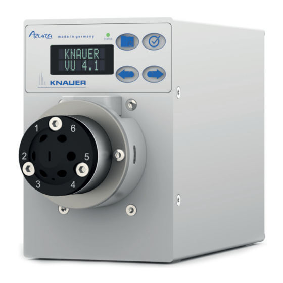
Otherwise, the protective and safety equipment of the device could fail. Description The valve drive AZURA® Valve Unifier VU 4.1 enables automatic valve switch- ing. The display provides an user friendly operation. Due to its low switching time, the flow path is interrupted only for a very short time, and the pressure peaks are reduced to a minimum. -
Page 6: Device Overview
External devices can be connected to the valve drive in three different ways: connected to terminal strip via LAN connector within a network via interface USB (virtual COM port) AZURA® Valve Unifier VU 4.1 Instructions V6855... -
Page 7: Status Display
LED shows the current status. Status Not ready The valve position must be set to Home. Blinking: Method in software is paused. Not blinking: Ready Blinking: Error Not blinking: Fatal error. Contact the Technical Support. Standby AZURA® Valve Unifier VU 4.1 Instructions V6855... -
Page 8: Rfid Icon
A new microprocessor for faster device performance New interfaces: dual IP stack with switch (for connecting AZURA devices to one another) and LAN stack function, plus USB (internal USB to RS-232) ser- vice interface. Both LAN connectors (1 and 2) can be used as interface or switch. - Page 9 Only use a given PEEK fitting for one specific port and never re-use it for other ports. Always install new PEEK fittings on each separate port. Follow KNAUER or manufacturer's instructions on caring for the columns More safety-relevant information is listed in alphabetical order in the follow- ing table: ...
-
Page 10: Signal Words
At any time, take the device completely out of operation by pulling the power plug from the power supply (wall mounted connector or power strip). Opening the module The device may only be opened by the KNAUER Technical Support or any company authorized by KNAUER. Signal words Possible dangers related to the device are distinguished in personal and material damages. -
Page 11: Symbols And Signs
Decontamination Report Devices without a completed Decontamination Report will not be repaired. If you would like to return a device to KNAUER, make sure to enclose a completed Decontamination Report with the device: https://www.knauer.net/... -
Page 12: Unpacking And Setup
Damage to the device by carrying or lifting it on protruding housing parts. The device may fall and thus cause injuries. Lift the device only centrally on the side of the housing. AZURA® Valve Unifier VU 4.1 Instructions V6855... -
Page 13: Power Supply
Electronic defect Electronic hazard when using an identically constructed power adapter from another manufacturer. Only use original parts and accessories made by KNAUER or a company authorized by KNAUER. Prerequisites The electrical power supply at the installation site must be connected directly to the nearest main power line. -
Page 14: Mounting The Valve Onto The Valve Drive
Connecting the device to the computer Note: IHPLC devices made by KNAUER work only with IP adresses which are assigned via IPv4. IPv6 is not supported. This section describes how to set up an HPLC system in a local area network (LAN) and how a network administrator can integrate this LAN into your com- AZURA®... -
Page 15: Configuring The Lan Settings
LAN into a wide area network (WAN), e.g. a company network or the Internet. In contrast, the LAN ports serve to set up a network from devices AZURA® Valve Unifier VU 4.1 Instructions V6855... -
Page 16: Configuring The Router
3. Configure the router as DHCP server. 4. In the router configuration, check the IP address range and make changes if necessary. Note: If the IP address range has been changed, it is necessary to note it down. AZURA® Valve Unifier VU 4.1 Instructions V6855... -
Page 17: Integrating The Lan Into A Company Network
The two LAN ports of the valve drive can be freely connected to the PC and/or with a LAN port to another device. Note that this other device can be connected to a third device etc., so you may add several devices in a row. AZURA® Valve Unifier VU 4.1 Instructions V6855... -
Page 18: Manual/Dhcp
Unpacking and setup Use the display to assign the IP address to manual or DHCP. In addition, all devices with AZURA Neo can be set via a "router-less" APIPA configuration. Manual/DHCP The IP address can be assigned via valve drive display. In the submenu "Drive Setup", you can assign whether the LAN control is set to manual or via DHCP. -
Page 19: Manual Control
Trigger signal: 2 position valve to position 2 multi position valve to position 1 No trigger signal: 2 position valve to position 1 multi position valve not to position 1 Reference point of the voltage at the signal inputs AZURA® Valve Unifier VU 4.1 Instructions V6855... -
Page 20: Binary Control
BIN 0 - BIN 3 are available as inputs. Binary code A binary code is entered during binary control so that the valve can be set externally in the correct position (nominal position). AZURA® Valve Unifier VU 4.1 Instructions V6855... -
Page 21: Ground Connection
Electronic hazard when using an identically constructed power adapter from another manufacturer. Only use original parts and accessories made by KNAUER or a company authorized by KNAUER. The valve drive has an icon for the ground connection on the rear of the device. -
Page 22: Operation
LAN port and a computer. The valve drive can be operated with one of the available chromatography data systems (OpenLAB® EZChrom Edi- tion, ClarityChrom®, Chromeleon™, PurityChrom® and Mobile Control Chrom). You find a detailed description on chromatography software in a cor- responding user manual. AZURA® Valve Unifier VU 4.1 Instructions V6855... -
Page 23: Operating With The Keypad
2. A cursor is situated in the value. Move the cursor with the navigation but- tons to the relevant spot. 3. Press selection button. The value can now be changed. 4. Using the navigation buttons, set the value. 5. Using the confirmation buttons, confirm the value. AZURA® Valve Unifier VU 4.1 Instructions V6855... -
Page 24: Menu Guide
Operation Menu guide Fig. 3 Menu guide scheme AZURA® Valve Unifier VU 4.1 Instructions V6855... -
Page 25: Start Display
Drive GLP Retrieve GLP data of the valve drive. DRIVE Valve GLP Retrieve GLP data of the valve. ALVE Rehome Reset the position of the valve drive to REHO Drive Home position. DRIVE AZURA® Valve Unifier VU 4.1 Instructions V6855... -
Page 26: Submenus
Out.Mode Set if the output control is set via OC Out.Mode or via TTL Confirm Set if changes of the valve position are Confirm mode applied immediately (OFF) or after mode confirmation (ON) AZURA® Valve Unifier VU 4.1 Instructions V6855... - Page 27 Selection of the total switching cycles Cycles of the mounted valves 56738 Serial Serial number of the mounted valve FWR16 Number 5100013 Valve Number of positions and ports of the Pos. Information mounted valve Ports 10 AZURA® Valve Unifier VU 4.1 Instructions V6855...
-
Page 28: Setting The Valve Position
4. Finish the process with pressing the confirmation but- ton. 5. Change to main display. 6. Use the navigation buttons to set a value for the posi- 1 / 4 tion. 7. Confirm the selection by pressing the confirmation button. AZURA® Valve Unifier VU 4.1 Instructions V6855... -
Page 29: Setting The Valve Drive Control
1. Change to LAN Setup display: Main Display > Drive Setup > LAN Setup SETUP 2. Press selection button. 3. Using the navigation buttons, navigate to the value that has to be changed. 4. Press selection button. AZURA® Valve Unifier VU 4.1 Instructions V6855... -
Page 30: Input
1. Change to Input display: Main Display > Drive Setup In.Pins > In.Pins Inputs 2. Press selection button. 3. Change the setting (Inputs/BinCode) via the naviga- tion buttons. 4. Finish the process with pressing the confirmation but- ton. AZURA® Valve Unifier VU 4.1 Instructions V6855... -
Page 31: Output
Setting valve position to Home In this menu point, the valve position can be set to Home. Process Figure 1. Change to main menu point Rehome Drive. REHO 2. Press confirmation button. DRIVE AZURA® Valve Unifier VU 4.1 Instructions V6855... -
Page 32: Exchanging Rotor Seal
Installation Qualification (IQ) The customer may request the Installation Qualification, which is free of charge. In case of a request, the Technical Support of KNAUER or from a pro- vider authorized by KNAUER performs this functionality test during the instal- lation. -
Page 33: Troubleshooting
The test intervals are dependent on the usage of the device. Execution The test can be carried out either by the Technical Support of KNAUER or from a provider authorized by KNAUER (for a fee). Troubleshooting Go through the following steps, in case no connection between the computer and the devices can be established. -
Page 34: Error Messages
Remount the device. Note: If it is not possible to solve the error based on this list or if a new error appears, restart the device. If the error reappears, contact the Technical Support. AZURA® Valve Unifier VU 4.1 Instructions V6855... -
Page 35: Maintenance And Care
Transport Carefully prepare the device for transport. If you want to return your device to KNAUER for repairs, enclose the Service Request Form which can be downloaded from our website. For a secure transport, note the weight and dimensions of the device (see chapter “Technical data”). -
Page 36: Repeat Orders
Repeat orders Repeat orders Valve drive and accessories Name Order no. Valve drive AZURA® Valve Unifier VU 4.1 AWA01 Accessory kit AZURA® Valve Unifier VU 4.1 FWA01 Power cable Name Order no. Power cable for Germany M1642 Power cable for UK... -
Page 37: Warranty Seal
A warranty seal is attached on some devices. The warranty seal is color- coded. A blue seal is used by the assembly or technical support of KNAUER for devices to be sold. After repair, service technicians stick an orange seal in identical position. - Page 38 Legal information factured by KNAUER back to the distributor, the importer, or the company free of charge, but would be charged for the disposal. Solvents and other operating materials All solvents and other operating materials must be collected separately and disposed of properly.
-
Page 39: Index
13 test problems 29 Installation Qualification 28 router 12 Operation Qualification 29 settings 11 transport 8 setup 11 transport damage 32 troubleshooting menu guide 20 error messages 30 multiposition valve 24 LAN 29 AZURA® Valve Unifier VU 4.1 Instructions V6855... - Page 40 Index valve mount 10 valve position 24 view front 2 rear 2 warranty 32 warranty seal 33 AZURA® Valve Unifier VU 4.1 Instructions V6855...
- Page 41 Latest KNAUER instructions online: https://www.knauer.net/en/Support/User-manuals © KNAUER 2018 Phone: +49 30 809727-0 KNAUER Fax: +49 30 8015010 Wissenschaftliche Geräte GmbH E-Mail: info@knauer.net Hegauer Weg 38 Internet: www.knauer.net 14163 Berlin...
Need help?
Do you have a question about the AZURA and is the answer not in the manual?
Questions and answers