
Related Manuals for Knauer Azura Assistant ASM 2.2L


Summary of Contents for Knauer Azura Assistant ASM 2.2L
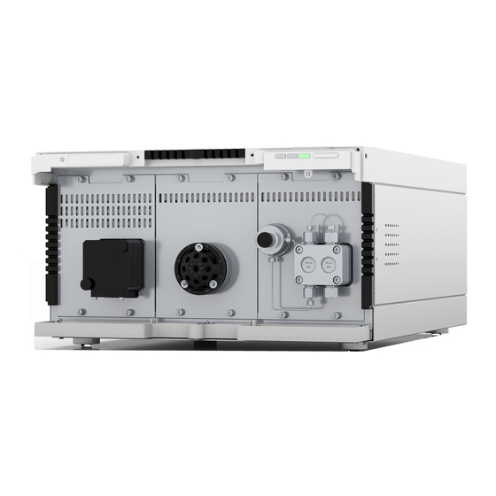
- Page 1 Assistant ASM 2.2L Instructions Sample configuration of ASM 2.2L with valve Document no.: V6803...
- Page 2 For latest version of the instructions, check our website: www.knauer.net/library. Copyright: This document contains confidential information and may not be repro- duced without written consent of KNAUER Wissenschaftliche Geräte GmbH. © KNAUER Wissenschaftliche Geräte GmbH 2024 All rights reserved. AZURA® is a registered trademark of...
-
Page 3: Table Of Contents
Table of contents 1. General ................1 About this instructions. - Page 4 Table of contents Device Overview ............14 Ordering and limitations of configuration .
- Page 5 Table of contents 12. Maintenance and Care ............. 48 12.1 Maintenance Contract .
-
Page 6: General
These operating instructions are an integral part of the device. It has to be kept in the immediate vicinity of the device and accessible to the user at all times. You can download these and other instructions from the KNAUER web- site: www.knauer.net/library. Signal words Possible dangers related to the device are distinguished in personal and material damages. -
Page 7: Legal Information
1.4.4 Warranty seal A blue or orange warranty seal is affixed to some devices. A blue seal is used by the assembly or technical support of KNAUER ƒ for devices to be sold. After repair, service technicians stick an orange seal in identical posi- ƒ... -
Page 8: Basic Safety Instructions
Operation in potentially hazardous areas without special and addition- ƒ al explosion protection. Contact the KNAUER Customer Support for more information. User qualification The user is qualified to handle the device if all of the following points apply: He has at least a basic knowledge of liquid chromatography. -
Page 9: Operator Responsibility
Basic safety instructions Operator responsibility The operator is any person who operates the device himself or leaves it to a third party for use and who bears the legal product responsibility for the protection of the user or third parties during operation. The obligations of the operator are listed below: Know and follow the applicable work safety regulations ƒ... -
Page 10: Working With Solvents
Basic safety instructions Working with solvents 2.6.1 General requirements The user is trained for handling different solvents. ƒ Note the recommended solvents and concentrations in these instruc- ƒ tions in order to avoid personal injury or damage to the device; for example, certain chemicals may cause PEEK capillaries to swell or burst (see chap. -
Page 11: Hazardous Area
Service request form and decontamination report Devices which are shipped without the completed document “Service request form and decontamination report” will not be repaired. If you would like to return a device to KNAUER, make sure to enclose the com- pleted document: www.knauer.net/service request. -
Page 12: Safe Operation Of The Device Modules
Leave room for air circulation: See paragraph “space requirements“. Electronic defect Electronic hazard when using an identically constructed power adapter from another manufacturer. Only use spare parts and accessories from KNAUER or a company authorized by KNAUER. Startup of the Device Device defect Changes of the ambient temperature cause condensation inside the device. -
Page 13: Detector And Flow Cells
Safe operation of the device modules Pin-header connection Electronic defect Electrostatic discharge can destroy the electronics. Wear a protective bracelet against electrostatic discharge and ground. Electronic defect Connecting cables to the multi-pin connector of a switched on device cau ses a short circuit. Turn off the device before connecting cables. -
Page 14: Pump
Safe operation of the device modules Cleaning the flow cells Performance reduction Oil drops can contaminate the flow cell. Do not use compressed air for drying. Connecting the Capillaries Component defect Damage to the flow cell due to excessive tightening. Observe the torque of the screw connection. -
Page 15: Valve Drive And Valves
Possible damage to the pump head due to over-tightened capillary fitting. Note the torque of the screw connection. Valve drive and valves There are no special safety instructions for the valve drive. Please observe the safety instructions for valves V 4.1: www.knauer.net/v6864_en. AZURA® Assistant ASM 2.2L Instructions V6803... -
Page 16: Symbols And Signs
4. Symbols and Signs The following table explains symbols and labels which are used on the device or the device modules, in the software or in the instructions: Symbol Meaning Device fulfills the requirements of the Conformité Européenne, which is confirmed by the Declaration of Conformity. -
Page 17: Product Information
5. Product information AZURA® L characteristics The AZURA® Assistant ASM 2.2L complies with the external structure of the devices of the AZURA® L product line. The front cover serves as a protection for the assistant and its users, ƒ but can also be removed. The Assistant is a sturdy device due to its large footprint and low cen- ƒ... -
Page 18: Performance Features
Product information Performance features Control You may control the assistant with a chromatography data system (OpenLAB®, ClarityChrom® and PurityChrom®) or with an optional touch display (Mobile Control). There are LAN and analogue interfaces avail- able. Thus, you can integrate the assistant into almost any LC system. GLP data The Mobile Control and supported software products (restricted in PurityChrom®) display or read GLP data, such as the operating hours... -
Page 19: Rear View
Product information 5.3.2 Rear view Legend Label with serial numbers and article numbers CE-marking UKCA-marking Integrator output Service interface LAN-Connection 1 LAN-Connection 2 Pin header Warning Mains connection 67 8 with mains switch On/off switch Fig. 2 ASM 2.2L rear view Warranty seal Device Overview The ASM 2.2L may be equipped with up to three modules. -
Page 20: Overview Of The Device Modules
Further details about the assistant and a list of the modules can be found at www.knauer.net/de/Systemloesungen/LC-Modul-Docking-Station. Overview of the device modules The ASM 2.2L may be equipped with the following device modules (plug- in modules): 5.6.1 Detector AZURA®... -
Page 21: Pump Azura® P 2.1S/P 4.1S
Product information Legend UV detector Fig. 3 UV detector AZURA® UVD 2.1S in ASM 2.2L 5.6.2 Pump AZURA® P 2.1S/P 4.1S The ASM 2.2L may be equipped with the AZURA® pumps P 2.1S and P 4.1S. Additionally the pump P 4.1S is equipped with a pressure sensor. Note: A maximum of two pumps are allowed in an assistant. -
Page 22: Valve Drive Azura® Valve Unifier Vu 4.1
The ASM 2.2L may be equipped with a maximum of three VU 4.1 valve drives. The valves V 4.1 are driven by the valve drive VU 4.1, but have to be ordered separately. An overview of the valves supported can be found at: www.knauer.net/valves-assistant. Legend Valve drive Fig. 5 Valve drive AZURA®... - Page 23 Product information 5.6.3.1 Mounting the valve onto the valve drive Preparation Before inserting the valve, check that the pin on the rear side of the valve is in a horizontal position (s. Fig. 6). The notch is on the left, the RFID tag points upwards.
-
Page 24: Sample Configuration
Product information Sample configuration: ASM 2.2L as AZURA® educational system (article no. A46002) Fig. 7 Compact HPLC system isocratic ® The AZURA Compact HPLC isocratic educational system is a small com- plete analytical isocratic HPLC system. Due to its compact dimensions, the system fits onto every laboratory bench. - Page 25 Product information Process Figure Remove module 1. Remove the front cover 2. Loosen the four loss-resistant screws crosswise using a Phillips screwdriver (size 1). 3. Carefully move the module out of the guide rails by pulling on the screw heads. Inserting the module 4.
- Page 26 Product information Process Figure 6. Tighten the four loss-resistant screws. 7. The assistant automatically detects the device modules and checks the configuration according to the chapter (see chap. “5.4 Device Overview“ on page 14). AZURA® Assistant ASM 2.2L Instructions V6803...
-
Page 27: Scope Of Delivery
6. Scope of delivery Note: Only use original parts and accessories made by KNAUER or a company authorized by KNAUER. AZURA® Assistant ASM 2.2L ƒ Device modules ƒ 24 V power supply and cable with inlet connector for non-heating ƒ... -
Page 28: Unpacking And Setup
7. Unpacking and setup Location requirements Note: Proper operation is only guaranteed if you adhere to the specifica- tions for the ambient conditions and the place of use. Before you specify the location, read the technical data (see chap. “15. Technical Data“... -
Page 29: Unpacking And Setup
Unpacking and setup Unpacking and setup Note: The leak sensor may malfunction it the device is placed on an inclined surface. Use a level to check that the device is in an horizontal position. Store all packing material. Retain included packing list carefully for repeat orders. -
Page 30: Power Supply
Electronic defect Electronic hazard when using an identically constructed power adapter from another manufacturer. Only use spare parts and accessories from KNAUER or a company authorized by KNAUER. The assistant is intended for use with AC power networks of 100-240 V. -
Page 31: Initial Startup
8. Initial startup Optional accessories such as mounting brackets, a tablet holder for the Mobile Control or AZURA® Click may be mounted during commissioning (see chap. “16. Accessories and spare parts“ on page 53). The instructions of the device modules contain all the information required for commis- sioning (see chap. -
Page 32: Connecting The Device To A Computer
Connecting the device to a computer Note: HPLC devices made by KNAUER work only with IP addresses which are assigned via IPv4. IPv6 is not supported. IPv6 is not supported. This chapter describes how to set up a chromatography system in a local area network (LAN) and how a network administrator can integrate this LAN into your company network. -
Page 33: Configuring The Lan Settings
Initial startup 8.2.1 Configuring the LAN Settings The LAN uses only one server (which is normally the router) from that the devices automatically receive their IP address. Prerequisites In Windows®, power saving, hibernation, standby, and screen saver ƒ has to be deactivated. In case you use an USB-to-COM box, the option "Allow the computer ƒ... -
Page 34: Configuring The Router
8.2.3 Configuring the Router The router is preset at the factory. Information about address, user name and password is noted in the router manual: www.knauer.net/de/Sup- port/Handbuecher/PC-Hardware. Procedure 1. To open the router configuration, start your Internet browser and en- ter the IP address (not for all routers). -
Page 35: Controlling Several Systems Separately In The Lan
Initial startup 8.2.5 Controlling several systems separately in the LAN Devices connected to a LAN communicate through ports, which are part of the IP address. If more than one chromatography systems are connect- ed to the same LAN and you plan on controlling them separately, you can use different ports to avoid interference. -
Page 36: Mobile Control: Setting Ip Address To Dhcp Via Device Name
Initial startup Prerequisites The device has been switched on. ƒ Mobile Control has been installed and started. ƒ The connection between the Mobile Control and the device has been ƒ established. Procedure 1. In Mobile Control choose <Settings> 2. On the <General> tab choose the device name. 3. -
Page 37: Firmware Wizard: Setting A Static Ip Address
Initial startup Procedure 1. In Mobile Control choose <Settings> 2. Under <Network Settings> click <Reset>. The window <Reset com- munication settings> opens. 3. Enter the serial number of the device in the text box. 4. Click <OK>. The device is now reset to factory settings. 5. -
Page 38: Firmware Wizard: Setting A Dynamic Ip Address
APIPA is a service that allows devices to obtain a dynamic IP address even without a DHCP server in the network. The AZURA® Neo platform from KNAUER supports APIPA. The device has to be set to DHCP for this. If no DHCP server responds, the APIPA implementation ensures that the device gives itself a random IP address from the IP address range reserved for APIPA (169.254.x.x). -
Page 39: Remote Control
Initial startup Remote control External devices like computers, fraction collectors, etc. may be connect- ed to the assistant in two different ways: Connected to terminal strip ƒ Connected to LAN within a network ƒ The single ports exchange start, control and error signals with other de- vices. -
Page 40: Pin Header Assignments
Initial startup 8.3.2 Pin header assignments 1 2 3 4 5 6 7 8 9 10 11 12 Fig. 17 Plug Connector assignments Connector Function Reference point of the voltage at the signal inputs. ANA OUT Voltage range 0 V – 10 V Depending on the used module in the ASM 2.2L, the pump pressure or the detector signal can be output. - Page 41 Initial startup Connector Function START IN TTL-compatible input Low-active ƒ Secure switching threshold at least 10 mA The start of a hold method which is stored in the ASM 2.2L device can be triggered by a signal (short circuit to GND) from an external device. Starting single modules with START IN is not support- TTL-compatible output(default setting)/ ERROR OUT...
-
Page 42: Integrator Output
Initial startup 8.3.3 Integrator output The integrator output sends signals of the detector or the pressure sen- sor. Non-bipolar ƒ 1 channel ƒ 0 - 2.5 V ƒ DAC 20 bit ƒ Scalable ƒ Adjustable to offset ƒ 8.3.4 Analog port You can find information about the analogue connection in the operating instructions of the respective device module. -
Page 43: Operation
To operate the device with software, you have to establish a connection software between the LAN port and a computer. A list of supported devices is available in the public area of the website at: www.knauer.net/softwarecontrol. You find a detailed description on chromatography software in a corre- sponding instruction. Mobile Control Mobile Control is an app which can be installed on your computer or tab- let. -
Page 44: Glp Data
Operation Color Operating condition Operation Center LED Does not light Not ready for operation Switch on the device. flashes green Detector is initializing/ Wait until the device is calibrating ready. green Ready for operation Right LED green Switched on (Operational status) blue Standby Exit with the standby... -
Page 45: Switch The Assistant On
The LAN connections between the modules and router are connected. ƒ The LAN cable is connected to the workstation and router. ƒ The chromatography software has been installed by KNAUER or a ƒ company authorized by KNAUER. The capillaries in the solvent bottles have an insert filter. -
Page 46: Activate Standby
Operation Activate standby Prerequisites The flow has been switched off. Note: Malfunctioning system after repeated standby possible. After repeatedly using the standby, switch off the power switch and back on again, to reset the data storage. Procedure Figure 1. Press the standby switch 5 seconds. -
Page 47: Functionality Tests
Installation Qualification The customer may request the Installation Qualification, which is free of (IQ) charge. In case of a request, the Technical Support of KNAUER or from a provider authorized by KNAUER performs this functionality test during the installation. The IQ is a standardized document and includes the following: Confirmation of flawless condition at delivery ƒ... -
Page 48: Troubleshooting
4. Check device for leaks. 5. Pay attention to system messages. Further measures Inform the technical support of KNAUER. 11.1 LAN Check the following, in case no connection between the computer and the devices can be established. Check after each step if the problem is solved. -
Page 49: Possible Problems And Rectifications
Change the ball valves. ƒ When the pump head seals are defec- ƒ tive, solvent enters the piston backflush- ing. Inform the Technical Support of KNAUER. Replace the pump head. ƒ AZURA® Assistant ASM 2.2L Instructions V6803... - Page 50 Inform the Technical Support of KNAUER. Replace the pump head. ƒ Valves Valve leaks Tighten the connections. Pressure variations Replace the rotor seals. caused by leaking valve head Further measures Inform the technical support of KNAUER. AZURA® Assistant ASM 2.2L Instructions V6803...
-
Page 51: System Messages
If other system messages are displayed besides those listed below, please turn the device off and then on. In case the system message re- peats itself, inform the Technical Support of KNAUER. The system messages are sorted alphabetically. System message... - Page 52 Troubleshooting System message Solution Leak sensor not present Switch the device off and then on. If the leak sensor is still not present, contact the Technical Support of the manufacturer. Leak was detected Switch off the device. Remove the leak and start the device afterwards.
-
Page 53: Maintenance And Care
12.1 Maintenance Contract The following maintenance work on the device may only be performed by KNAUER or a company authorized by KNAUER and is covered by a separate maintenance contract: Opening the device. ƒ... -
Page 54: Maintenance Tasks For Users
Maintenance and Care 12.4 Maintenance tasks for users For information according to maintenance, care and the recommended intervals, refer to the operating instructions of the respective device mod- ules. 12.5 Preparing the assistant for storage or trans- port Pay attention that all hoses and capillaries have been emptied or filled with flushing solution (e. -
Page 55: Transport And Storage
Do not hold onto front cover or leak tray, as these parts are loosely attached to the device. 13.3 Transporting the device Documents: If you want to return your device to KNAUER for repairs, ƒ enclose the “Decontamination report“... -
Page 56: Disposal
All distributors and importers are responsible for the disposal of old devices, as defined by the WEEE directive. KNAUER devices may not be disposed of with household waste. For devices purchased directly from KNAUER, KNAUER will bear the costs of disposal. -
Page 57: Technical Data
15. Technical Data Note: Also note the technical data of the integrated device modules in the corresponding instructions. 15.1 Communication Port Control Mobile Control ƒ Software ƒ Inputs Error (IN), Start (IN), Autozero, 0-10 V Analog IN Outputs Event 1–2, Error (OUT) (OC), +5 V, +24 V Analog outputs Integrator output (detector signal, pump pressure) -
Page 58: Accessories And Spare Parts
16. Accessories and spare parts Note: If a compact HPLC was ordered, tools and capillaries are within the scope of delivery. The torque wrench for pumps is not within the scope of delivery. Name Order number ASM 2.2L, basic unit with two empty modules AYASM Device modules Empty module... - Page 59 Accessories and spare parts Name Order number AZURA® Click for attaching IFU 2.1, airsensor, pressure A70089 control Accessory kits Accessory kit AZURA® L devices FZA02 AZURA® Accessory kit AZURA® P 2.1S and P 4.1S FPGA Accessory kit AZURA® UVD 2.1S and UVD 2.1L Accessory kit AZURA®...
-
Page 60: Chemical Compatibility Of Wetted Materials
The following list contains information about the chemical compatibility of all wetted materials which are used in devices made by KNAUER. The data bases on a literature research on the manufacturer specifications of the materials. The wetted materials of this device are listed in the chapter “Technical data”. - Page 61 Polyimide (Vespel®) This material is wear-resistant and permanent resilient thermically (up to 200 °C) as well as mechanically. It is chemically broadly inert (pH range 1 - 10) and is especially resistant against acidic to neutral and organic solvents, but vulnerable to pH strong chemical or oxidizing environments: It is incompatible with concentrated mineral acids (such as sulfuric acid), glacial acetic acid, DMSO and THF.
-
Page 62: Non-Metals
Polychlortrifluorethylene (PCTFE, Kel-F®) The semi-crystalline thermoplastic material is plasticizer-free and dimen- sionally stable, even in a wide temperature range (−240 °C to +205 °C). It is moderately resistant against ether, halogenated solvents and toluene. Halogenated solvents over +60 °C and chlorine gas should not be used. Fluorinated rubber (FKM) The elastomer consisting of fluorinated hydrocarbon stands out due to a high resistance against mineral oils, synthetic hydraulic fluids, fuels,... -
Page 63: Metals
Mineral wool This insulating material consists of glass or stone wool fibres and isolates in high oxidizing conditions and at high temperatures. Mineral wool is valid as commonly inert against organic solvents and acids. Glass, glass fibre, quartz, quartz glass These mineral materials are resistant against corrosion and wear and are mostly chemical inert. - Page 64 Customer approval Prior to installation at the customer site, the customer has reviewed the OQ document and agrees with the design and scope. Company name: Name Function Reviewed & approved Date Signature VIQ-Installation-Qualification-Device, Version 3.1 Date: Signature: Revision:...
- Page 65 KNAUER Wissenschaftliche Geräte GmbH. Scope The customer can request the Installation Qualification. In case of a request, the technical support of KNAUER or a provider authorized by KNAUER performs this functionality test during the installation. The IQ is a standardized document and includes the following: ƒ...
- Page 66 Installation Qualification Tests Test Description Specification Passed Failed Comment /LOR No. Identify the device. The name on the device matches the name on the delivery order. Check the device for No transport damage is transport damage. observed. Check the scope of The scope of delivery delivery.
- Page 67 List of rectifications (LOR) Type of Description of Persons LOR No. Test No. Action plan Due date Date/signature deviation* the deviation responsible * Type of deviation: A = acceptable (e.g. not a GMP-critical deviation) N = not acceptable Continuation of qualification activities into the next qualification phase is only possible when deviation is rectified. T = temporarily acceptable a) Release and use of the system is possible, even when the deviation is not rectified.
- Page 68 List of changes to the document Revision no. Description of change Additional information Date/signature VIQ-Installation-Qualification-Device, Version 3.1 Date: Signature: Revision:...
- Page 69 Installation Qualification (IQ) for a Device 10. Certificate and approval A KNAUER employee or an employee authorized by KNAUER has checked the device and performed all tests described in the IQ. The IQ form has to be signed by an authorized person. The scope of the IQ meets the customer‘s requirements.
- Page 70 Appendix: List of supporting documents Test no. Description VIQ-Installation-Qualification-Device, Version 3.1 Date: Signature: Revision:...
- Page 71 Latest KNAUER instructions online: www.knauer.net/library KNAUER Phone: +49 30 809727-0 Wissenschaftliche Geräte GmbH Fax: +49 30 8015010 Hegauer Weg 37-38 E-mail: info@knauer.net 14163 Berlin Internet: www.knauer.net © KNAUER 2024...
Need help?
Do you have a question about the Azura Assistant ASM 2.2L and is the answer not in the manual?
Questions and answers