Table of Contents
Advertisement
Quick Links
Advertisement
Table of Contents

Related Manuals for Knauer AZURA IJM NanoScaler


Summary of Contents for Knauer AZURA IJM NanoScaler
- Page 1 IJM NanoScaler System Instructions Document no. V6776...
- Page 2 KNAUER. Support: Do you have questions about the installation or the operation of your instrument or software? International Support: Contact your local KNAUER partner for support: www.knauer.net/en/Support/Distributors-worldwide Support in Germany (Austria & Switzerland on case-to-case basis): Phone:...
-
Page 3: Table Of Contents
Table of contents 1. General ................1 About these instructions . - Page 4 Table of contents 4. Operation modes ..............14 5.
- Page 5 Table of contents 7. Functionality tests ..............44 Installation Qualification (IQ) .
-
Page 6: General
These operating instructions are an integral part of the device. It must be kept in the immediate vicinity of the device and accessible to the user at all times. You can download these and other instructions from the KNAUER web- site: www.knauer.net/library... -
Page 7: Legal Information
1.4.4 Warranty seal A blue or orange warranty seal is affixed to some devices. A blue seal is used by KNAUER’s Manufacturing or Customer Support ƒ for devices to be sold. After repair, service technicians attach an orange seal onto the identi- ƒ... -
Page 8: Basic Safety Instructions
Operation in potentially explosive areas without special and addition- ƒ al explosion protection. Contact the KNAUER Customer Support for more information. User qualification The users are qualified to handle the device if all of the following points... -
Page 9: Operator Responsibility
Basic safety instructions Operator responsibility The operator is any person who operates the device himself or leaves it to a third party for use and who bears the legal product responsibility for the protection of the user or third parties during operation. The obligations of the operator are listed below: Know and follow the applicable work safety regulations ƒ... -
Page 10: Working With Solvents
Basic safety instructions Working with solvents 2.6.1 General requirements The user is trained for handling different solvents. ƒ Note recommended solvents and concentrations in these instructions ƒ in order to avoid personal injury or damage to the device. For exam- ple, certain chemicals may cause PEEK capillaries to swell or burst (see “14 Chemical compatibility of wetted materials”, p. -
Page 11: Specific Environments
Devices which are shipped without the completed document “Service request form and decontamination report” will not be repaired. If you would like to return a device to KNAUER, make sure to enclose the com- pleted document: www.knauer.net/servicerequest IJM NanoScaler System Instructions, V6776... -
Page 12: Product Information
Otherwise, the protective and safety equipment of the system could fail. KNAUER‘s benchtop IJM NanoScaler system is designed for lab-scale lipid nanoparticle formulation – allowing scientists to screen for optimal process parameters to formulate API-containing lipid nanoparticles. -
Page 13: Formulation Parameters
Product information These active pharmaceutical ingredients include complex or delicate API like RNA, mRNA, siRNA, and DNA-based molecules, or products that need specific entry into target cells. In addition, researchers can use their own custom mixing unit and benefit from the flexibility of the system set- up. -
Page 14: Scope Of Delivery
Product information Scope of delivery 3.4.1 IJM NanoScaler (standard configuration) Note: Only use original parts and accessories made by KNAUER or a company authorized by KNAUER. 1 x AZURA® Assistant ASM 2.2L with 2 x AZURA® Pump P 4.1S ƒ (50 ml pump head) and 1 x 6-Port-2-position-valve 1 x AZURA®... -
Page 15: Views
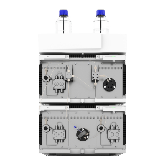
Product information Views 3.5.1 Front view Legend Lipid pump Quench pump Impingement Jets Mixer (IJM) Fractionation valve API pump API loop Fig. 2 IJM system components IJM NanoScaler System Instructions, V6776... -
Page 16: Rear View
Product information 3.5.2 Rear view Legend UKCA marking CE marking Label with serial numbers and article numbers Warranty seal On/off switch Mains connection with mains switch Warning bm 9 Pin header LAN-Connection 2 Fig. 3: ASM 2.2L, rear view LAN-Connection 1 Service interface Integrator output Meaning of the LEDs... - Page 17 Product information The LEDs can have different colors depending on the operating conditions. Color Operating condition Operation Left LED flashes red Error message Check the system. Shortly press the switch to deactivate the error message. Serious error Restart the device. If the operating condition does not change, call the technical support.
-
Page 18: Symbols And Signs
Product information Symbols and signs The following symbols and signs can be found on the device: Symbol Meaning Electric shock hazard. Failure to observe this warn- ing may result in loss of life, serious injury, or dam- age to or destruction of the device. Electrostatic discharge hazard. -
Page 19: Operation Modes
4. Operation modes In the standard configuration the IJM NanoScaler can be operated in two different modes. Fig. 5 Flow scheme of the NanoScaler in R&D mode The standard operation mode of the IJM NanoScaler is the R&D mode (see Fig. 5). Thereby small API volumes can be encapsulated by the usage of the integrated sample loop. - Page 20 Operation modes Fig. 6 Flow scheme of the NanoScaler in R&D+ mode The R&D mode of the standard IJM NanoScaler can be upgraded to the R&D+ mode (upgrade needs to be ordered separately, see chapter „13. Reorders“ on page 53). The upgrade features a second loop in an addi- tional valve to apply small volumes of lipids via a sample loop (see Fig.
-
Page 21: Installation And Initial Startup
Note: The intended use is only ensured if the requirements for ambient conditions of the operating environment are met. The IJM System will be set up, installed and commissioned by KNAUER or a company authorized and contracted by KNAUER. Note:... -
Page 22: Ambient Temperature
Power supply Electronic defect Electronic hazard when using an identically constructed power adapter from another manufacturer. Only use spare parts and accessories from KNAUER or a company authorized by KNAUER. Power supply requirements Failure-free power supply: For failure-free operation, the electrical ƒ... -
Page 23: Connecting The Capillaries
Country-specific plugs: Before switching on the device, check whether ƒ the supplied plug is approved for your country. Overview of the de- vice- and country-specific plug types from KNAUER: www.knauer.net/plugs Power strips: If several devices are connected to one power strip, al- ƒ... -
Page 24: Initial Start-Up Checklist
Devices are positioned in the correct location. ƒ The power plugs are connected. ƒ The network connection is established. ƒ The software has been installed by KNAUER or a company authorized ƒ by KNAUER. The capillaries are connected. ƒ SOP: IJM System power-up and shut-down 5.7.1... -
Page 25: Shut Down
Installation and initial startup 5.7.2 Shut down Procedure Steps 1. Close the software. 2. Turn off the PC. 3. Turn off all instruments. 4. Turn off the switch (if available). SOP: IJM System start-up Follow this procedure to perform an IJM system start-up. When delivered the system is filled with 80 % water / 20 % isopropanol. -
Page 26: Sop - Nanoscaler
Installation and initial startup SOP – NanoScaler 5.9.1 Back piston flushing By backflushing the piston regularly, you increase the service life of the seals and piston and remove impurities from the area behind the seals. Back piston flushing should be performed at least once a day. Procedure Steps 1. -
Page 27: Preparation
Installation and initial startup 5.9.2 Preparation Procedure Steps 1. Choose between the R&D or production mode and the IJM being used. Configure the system according to your selection. 2. Open the purge valve of pump 1 (Lipid) and and use a silicone tubing to connect the capillary next to the purge valve with a syringe. - Page 28 Installation and initial startup sample injection sample loop waste pump Fig. 11: Injection valve, position 2, sample injection Pump 3 Quench Valve 2 Pump 2 Pump 1 Lipid Fig. 12: NanoScaler R&D mode IJM NanoScaler System Instructions, V6776...
- Page 29 Installation and initial startup Procedure Loop filling Procedure Steps 1. A syringe is used to fill the sample loop. Fill the syringe with API solution and place it to the injection valve using a luer adapter. Fig. 13: Loop filling 2.
-
Page 30: R&D+ Mode
Installation and initial startup Pump 3 Mixer Quench Valve 3 Valve 2 Pump 2 Pump 1 Lipid Valve 1 Fig. 14: NanoScaler R&D+ mode 5.9.4 R&D+ mode In R&D+ mode, tests can be carried out with small volumes of API and lipids. -
Page 31: Production Mode
Installation and initial startup 5.9.5 Production mode Pump 3 Mixer Quench Valve 2 Pump 1 Pump 2 Lipid Valve 1 Fig. 15: NanoScaler Production mode In production mode, the API can be delivered directly to the IJM by pump 2. For this purpose, the CA09 capillary is connected directly from the pressure sensor of pump 2 to the IJM bottom port. -
Page 32: Api/Lipid Supply By Syringe (Optional)
Installation and initial startup 5.9.6 API/Lipid supply by syringe (optional) The API/Lipid supply by syringe is not part of the scope of delivery. Order article number A71100 separately if needed. Tool Offset screwdriver, size TX10 ƒ Procedure Steps 1. Screw the clamp to the upper screw connection of the lower assis- tance module next to the API pump by using the offset screwdriver TX10. -
Page 33: Cleaning The System
Installation and initial startup Procedure Steps 5. Then open the stopcock. Fig. 18: Syringe after opening the stopcock 6. For the first use of the syringe, the pump must be purged. Other- wise, skip to step 10. 7. Open the purge valve of pump 2 (API) and connect it to a syringe with a silicon tubing. -
Page 34: Single Ijm Cleaning Procedure
Installation and initial startup 5.11 Single IJM cleaning procedure Note: KNAUER recommends to carry out one of these cleaning procedu- res under the following circumstances: Change of IJMs ƒ Clogging of IJM ƒ Cleaning the IJM manually is necessary when a blockage occurs. Indica- tions are sudden increases in pressure of the API or lipid pump. - Page 35 Installation and initial startup Procedure Steps 8. Repeat the procedure from steps 4 - 5 (ethanol step is not needed) by placing the luer adapter and the syringe on the API port and the blind plug on the lipid port (Fig. 20). Use a beaker to collect the waste of the open port.
-
Page 36: Intermediate System Cleaning
Installation and initial startup 5.12 Intermediate system cleaning Note: KNAUER recommends to carry out this cleaning procedure under the following circumstances: Change of Lipid and/or API composition between different formula- ƒ tion cycles during the same day. Change of buffers. -
Page 37: Cleaning The Full System
Repeat step 2. Step 5 Repeat step 1. 5.13 Cleaning the full system Note: KNAUER recommends to carry out this cleaning procedure under the following circumstances: Before starting to work with the system. ƒ At the end of a working day. - Page 38 Installation and initial startup Pump 1 Pump 2 with Pump 3 (optional Valve 1 Valve 3) Valve position V1&3 Inject Drain Flush system for 30 min Load Product Flush system for 30 min Step2 Pump 1 Pump 2 with Pump 3 (optional Valve 1 Valve 3) Solvent...
-
Page 39: Recommended Flow Rates For Different Ijms
Installation and initial startup Step 4 Repeat step 2. Step 5 Repeat step 1. 5.14 Recommended flow rates for different IJMs The following table contains the recommended flow rates for each IJM. Note: The maximum operating parameters for flow and pressure depend on the viscosity of the solvents, the customer application, the inner diameter of the capillaries used and the back pressure spike caused by switching the valves. -
Page 40: Computer Control
The description applies to the operating system Win- dows® and all conventional routers. Note: LNP devices from KNAUER only work with IP addresses, which have been assigned by IPv4. IPv6 is not supported. Note: The devices of the IJM NanoScaler are set to fixed IP adresses. We recommend not to change the settings. -
Page 41: Connecting Devices With Lan
Computer control Process Procedure 1. In Windows, open <Network and Sharing Center>. 2. Double-click on <LAN connection>. 3. Click on the button <Properties>. 4. Select <Internet Protocol version 4 (TCP/IPv4)>. 5. Click on the button <Properties>. 6. Check the settings in the tab <General>. The correct settings for the DHCP client are: a) Obtain an IP address automatically b) Obtain DNS server address automatically... -
Page 42: Configuring The Router
Set the router properties (see section 6.4). Next steps Configuring the router The router is preset at the factory. Information about address, user name and password is noted in the router manual: www.knauer.net/router. Process Procedure 1. To open the router configuration, start your Internet browser and enter the IP address (does not apply for all routers). -
Page 43: Controlling Several Systems Separately In Lan
Computer control Controlling several systems separately in Devices connected to a LAN communicate through ports, which are part of the IP address. If more than one chromatography systems are connec- ted to the same LAN and you plan on controlling them separately, you can use different ports to avoid interference. -
Page 44: Mobile Control: Setting A Dynamic Ip Address Via Device Name
Computer control Process 3. In <Network Settings>, choose the setting <Static> 4. Enter the IP address into the text box <IP Address> 5. If necessary, change the subnet mask and the gateway 6. Click in the top right corner. 7. Restart the device (recommended). Legend IP address mode Text box for IP... -
Page 45: Mobile Control: Setting A Dynamic Ip Address Via Device Serial Number
Computer control Legend IP address mode Fig. 24: Network settings for dynamic IP address Result The device is now accessible via a dynamic IP address. 6.7.3 Mobile Control: Setting a dynamic IP address via device serial number Prerequisites The device is switched on. ƒ... -
Page 46: Firmware Wizard: Setting A Static Ip Address
Computer control 6.7.4 Firmware Wizard: Setting a static IP address Note: More information about LAN settings can be found in the Mobile Control Software Instructions in the chapter "Firmware Wizard” (docu- ment no. V6851-2). Legend Text box for serial number of the device Setting IP address manually Text box for... -
Page 47: Firmware Wizard: Setting A Dynamic Ip Address
Computer control 6.7.5 Firmware Wizard: Setting a dynamic IP address Prerequisites The device is switched on. ƒ Firmware Wizard is installed and running. ƒ Process Procedure 1. In Firmware Wizard, click <Reset LAN Settings...>. 2. The window <Device connection settings> opens. Enter serial number of the device into the text field <Target device serial number>... -
Page 48: Connecting The Pin Header
Computer control Connecting the pin header To control one device through another, the pin header is used. To use remote control, you have to connect cables to the pin header. The single ports are used to exchange control signals. Prerequisites The device is switched off. -
Page 49: Functionality Tests
Installation Qualification (IQ) The customer may request the Installation Qualification, which is free of charge. In case of a request, the technical support of KNAUER or a pro- vider authorized by KNAUER performs this functionality test during the installation. -
Page 50: Troubleshooting
8. Troubleshooting First measures Check all cables and fittings. ƒ Check all screw fittings. ƒ Check whether air has entered the supply lines. ƒ Check the device for leaks. ƒ Pay attention to system messages. ƒ Further measures: Compare occurring errors with the list of possible errors (see below). ƒ... -
Page 51: Possible Problems And Solutions
Troubleshooting 7. Make sure that the IP port of the device matches the port that is set in the chromatography software. Possible problems and solutions Note: If you have problems with the handling of a single device, please refer to the troubleshooting section of the respective instructions. Problem Possible Cause Solution... -
Page 52: Maintenance And Care
9. Maintenance and care Removing a leakage Prerequisites The device has been switched off. Material Cloth Procedure Process 1. Remove the leakage. 2. Dry the leakage tray with the cloth. 3. Confirm the error message via the chromatography software. Next step Put the device back into operation. -
Page 53: Transport And Storage
Do not hold onto front cover or leak tray, as these parts are loosely attached to the device. 10.3 Transporting the device Documents: If you want to return your device to KNAUER for repairs, ƒ enclose the „Service request form and decontamination report“which... -
Page 54: Disposal
160214. 11.2 WEEE registration number KNAUER as a company is registered by the WEEE number DE 34642789 in the German "Elektroaltgeräteregister" (EAR). The number classifies to category 8 and 9, which, among others, comprises laboratory equipment. -
Page 55: Technical Data
12. Technical data 12.1 General system parameters Number of Impingement 5, IJM 1-5 manual selection Jets mixer Number of pumps Number of valves 1/8“ OD, 2.1 mm, ID FEP tubing Process connection inlet (UNF 1/4-28 thread, flat bottom) Process connection outlet 1/16“... -
Page 56: Wetted Materials
Technical data Power consumption Docking station (including pumps and valves): (per device) maximum 130 W; network switch: 50 W Dimensions 361 mm x 501 mm x 603 mm (Width × Height × Depth) Net weight (approx.) 35 kg 12.3 Wetted materials Note: For chemical compatibility of wetted materials see chapter “14. - Page 57 Technical data Material Description Valves Polyetheretherketone (Rotor seal) PEEK Stainless steel DLC* (Stator) AISI 318LN * stainless steel, coated with diamond-like carbon Material Description Capillaries & fittings Stainless steel AISI 316L (1.4404) Polyetheretherketone PEEK Polyoxymethylene Ethylene tetrafluoroethylene ETFE Material Description Sample loops Stainless steel AISI 316L (1.4404)
-
Page 58: Reorders
If you have any questions regarding spare parts or accessories, please contact our Customer Support. Further information Current information on spare parts and accessories can be found on the Internet at www.knauer.net. 13.1 Device Name Order no. Pump P 4.1S APG22FA* Pump P 4.1S... - Page 59 Reorders Name Order no. Capillaries Reorder PEEK capillary set IJM NanoScaler, without A71102 screw connections Reorder set lipid loop, capillaries only A71103-1 PEEK capillaries IJM NanoScaler, with screw F48040 connections API/Lipid supply kits API/Lipid, starter kit A71100 API/Lipid, refill kit A71101 Tubing Tubing kit, pump inlet...
-
Page 60: Chemical Compatibility Of Wetted Materials
The following list contains information about the chemical compatibility of all wetted materials which are used in devices made by KNAUER. The data bases on a literature research on the manufacturer specifications of the materials. The wetted materials of this device are listed in the chapter “Technical data”. - Page 61 Chemical compatibility of wetted materials Polyimide (Vespel®) This material is wear-resistant and permanent resilient thermically (up to 200 °C) as well as mechanically. It is chemically broadly inert (pH range 1-10) and is especially resistant against acidic to neutral and organic solvents, but vulnerable to pH strong chemical or oxidizing environments: It is incompatible with concentrated mineral acids (such as sulfuric acid), glacial acetic acid, DMSO and THF.
-
Page 62: Non-Metals
Chemical compatibility of wetted materials Polychlortrifluorethylene (PCTFE, Kel-F®) The semi-crystalline thermoplastic material is plasticizer-free and dimen- sionally stable, even in a wide temperature range (−240 °C to+205 °C). It is moderately resistant against ether, halogenated solvents and toluene. Halogenated solvents over +60 °C and chlorine gas should not be used. Fluorinated rubber (FKM) The elastomer consisting of fluorinated hydrocarbon stands out due to a high resistance against mineral oils, synthetic hydraulic fluids, fuels,... -
Page 63: Metals
Chemical compatibility of wetted materials Mineral wool This insulating material consists of glass or stone wool fibres and isolates in high oxidizing conditions and at high temperatures. Mineral wool is valid as commonly inert against organic solvents and acids. Glass, glass fibre, quartz, quartz glass These mineral materials are resistant against corrosion and wear and are mostly chemical inert. - Page 64 Installation Qualification (IQ) for a System Customer pre-approval Prior to installation at the customer site, the customer has reviewed the IQ document and agrees with the design and scope. Company name: Name Function Reviewed & approved Date Signature VIQ-Installation-Qualification-System Version 3.0 Revision: Page 1/7...
- Page 65 KNAUER Wissenschaftliche Geräte GmbH. Scope The customer can request the Installation Qualification. In case of a request, the technical support of KNAUER or a provider authorized by KNAUER performs this functionality test during the installation. The IQ is a standardized document and includes the following: ƒ...
- Page 66 Installation Qualification (IQ) for a System Installation Qualification Tests Test Description Specification Passed Failed Comment /LOR No. Identify the system. The article number and project number (made up of customer/order number) on the label attached to the skid frame matches the article number and customer/order number on the packing list.
- Page 67 Installation Qualification (IQ) for a System List of rectifications (LOR) Type of Description of Persons LOR No. Test No. Action plan Due date Date/signature deviation* the deviation responsible * Type of deviation: A = acceptable (e.g. not a GMP-critical deviation) N = not acceptable Continuation of qualification activities into the next qualification phase is only possible when deviation is rectified.
- Page 68 Installation Qualification (IQ) for a System List of changes to the document Revision no. Description of change Additional information Date/signature VIQ-Installation-Qualification-System Version 3.0 Revision: Page 5/7...
- Page 69 Installation Qualification (IQ) for a System 10. Certificate and appoval A KNAUER employee or an employee authorized by KNAUER has checked the device and performed all tests described in the IQ. The IQ form has to be signed by an authorized person. The scope of the IQ meets the customer‘s requirements.
- Page 70 Installation Qualification (IQ) for a System Appendix: List of supporting documents Test no. Description VIQ-Installation-Qualification-System Version 3.0 Revision: Page 7/7...
- Page 71 Latest KNAUER instructions online: www.knauer.net/library KNAUER Phone: +49 30 809727-0 Wissenschaftliche Geräte GmbH Fax: +49 30 8015010 Hegauer Weg 38 E-mail: info@knauer.net 14163 Berlin Internet: www.knauer.net © KNAUER 2023...
Need help?
Do you have a question about the AZURA IJM NanoScaler and is the answer not in the manual?
Questions and answers