Table of Contents
Advertisement
Quick Links
Advertisement
Table of Contents

Related Manuals for Knauer Azura Detector UVD 2.1S


Summary of Contents for Knauer Azura Detector UVD 2.1S
- Page 1 Detector UVD 2.1S Instructions HPLC Document no. V6820...
- Page 2 For the printed versions of our instructions, we use environmentally friendly paper from sustainable forests. Copyright: This document contains confidential information and may not be reproduced without written consent of KNAUER Wissenschaftliche Geräte GmbH. © KNAUER Wissenschaftliche Geräte GmbH 2019 All rights reserved.
-
Page 3: Table Of Contents
Table of contents 1. General ................1 About these instructions . - Page 4 Setting the optical path length of a preparative flow cell ..... 12 Connecting capillaries........... 13 Switching on the detector .
- Page 5 Rinsing the flow cell ........... . . 37 8.5.1 Cleaning the lens of an analytical flow cell .
-
Page 6: General
These operating instructions are an integral part of the device. It must be kept in the immediate vicinity of the device and accessible to the user at all times. You can download these and other instructions from the KNAUER web- site: www.knauer.net/library... -
Page 7: Legal Information
1.4.3 Warranty conditions For information on warranty please refer to our general terms and condi- tions on the website: www.knauer.net/terms 1.4.4 Declaration of conformity The declaration of conformity is enclosed as a separate document with the product and can be obtained online: www.knauer.net/en/Support/Declarations-of-conformity... -
Page 8: Foreseeable Misuse
Operation in potentially explosive areas without special and additio- ƒ nal explosion protection. Contact the KNAUER Customer Support for more information. User qualification The user is qualified to handle the device if all of the following points apply: He has at least a basic knowledge of liquid chromatography. -
Page 9: Personal Safety Equipment
Basic safety instructions Personal safety equipment The protective measures required in the laboratory must be observed and the following protective clothing worn during all work on the device: Safety glasses with side protection ƒ Protective gloves in accordance with the prevailing ambient conditions ƒ... -
Page 10: Specific Environments
Devices which are shipped without the completed document “Service request form and decontamination report” will not be repaired. If you would like to return a device to KNAUER, make sure to enclose the com- pleted document: www.knauer.net/servicerequest AZURA® Detector UVD 2.1S Instructions, V6820... -
Page 11: Product Information
3. Product information Features One of the smallest HPLC detectors on the market. ƒ A wide range of flow cells for analytical or preparative LC applications ƒ with flow rates from 10 µl/min up to 10 l/min. Automatic recognition and storage of device-specific information, ƒ... -
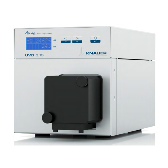
Page 12: Views
Product information Views Front view Legend Display Keyboard Flow cell Fig. 1 Front view Rear view Legend RS-232 port LAN port Pin header Integrator output Connection Ground Fig. 2 Rear view AZURA® Detector UVD 2.1S Instructions, V6820... -
Page 13: Symbols And Signs
Product information Symbols and signs The following symbols and signs can be found on the device: Symbol Meaning High-voltage hazard Electrostatic discharge hazard, damages to sys- tem, device, or components can occur. A device marked with CE fulfills the product spe- cific requirements of European directives. -
Page 14: Installation And Initial Startup
4. Installation and initial startup Before you determine the operation site, read chapter 11 on page 43. There you will find all device-specific information on power supply, am- bient conditions and humidity. Note: The intended use be ensured only if the requirements for ambient conditions of the operating environment are met. -
Page 15: Space Requirements
Country-specific plugs: Before switching on the device, check whether ƒ the supplied plug is approved for your country. Overview of the de- vice- and country-specific plug types from KNAUER: www.knauer.net/plugs Power strips: If several devices are connected to one power strip, al- ƒ... -
Page 16: Initial Startup
Installation and initial startup Initial startup Note: Before the detector is ready for use, a flow cell must be installed. Before installing the flow cell, the optical path length in the flow cell can be changed. The optimal path length depends on the type and the quan- tity of the sample. -
Page 17: Setting The Optical Path Length Of A Preparative Flow Cell
Installation and initial startup Setting the optical path length of a prepa- rative flow cell Depending on type, the path length is factory set to 2 mm, 3 mm, or 10 mm. For the 2 mm flow cells you can remove the spacers on one or both sides and hence change the path length to 1.25 mm or 0.5 mm. -
Page 18: Connecting Capillaries
Installation and initial startup Connecting capillaries Component defect Damage to components due to excessive tightening possible. Observe the torque of the screw connection Use 5 Nm torque for stainless steel fi ttings. Use 1 Nm torque for PEEK fi ttings. Note: PEEK fittings withstand a maximum pressure of 400 bar. Prerequisite Flow cell is removed from the detector. - Page 19 Installation and initial startup Process 1. Connect the power cable with the device. Procedure 2. Connect the power supply unit with the power cable.. 3. Connect the power supply unit with the power supply. 4. Using the power supply switch, switch on the detector. Result The detector starts its self-calibration.
-
Page 20: Computer Control
Installation and initial startup Computer control Note: HPLC devices from KNAUER only work with IP addresses, which have been assigned by IPv4. IPv6 is not supported. This chapter describes how to set up a chromatography system in a local area network (LAN) and how a network administrator can integrate this LAN into your company network. -
Page 21: Connecting Devices With Lan
Next steps Set the router properties (see section 4.8.4). 4.8.4 Configuring the router The router is preset at the factory. Information about address, user name and password is noted in the router manual: www.knauer.net/router AZURA® Detector UVD 2.1S Instructions, V6820... -
Page 22: Integrating Lan Into The Company Network
Installation and initial startup Process Procedure 1. To open the router configuration, start your Internet browser and enter the IP address (does not apply for all routers). 2. Enter user name and password. 3. Configure the router as DHCP server. 4. -
Page 23: Setting Ip Addresses Via Software
Installation and initial startup Setting IP addresses via software Note: Check the IT security standards for your lab before intervening in the LAN settings. Static IP addresses are required to run certain chromatography software, PurityChrom® e.g. Purity Chrom®. For a comprehensive overview on how to set static IP addresses for PurityChrom®, refer to the document „PurityChrom®... -
Page 24: Mobile Control: Setting A Dynamic Ip Address Via Device Name
Installation and initial startup 4.9.2 Mobile Control: Setting a dynamic IP address via device name Prerequisites The device is switched on. ƒ Mobile Control is installed and running. ƒ The connection between Mobile Control and the device has been ƒ established. -
Page 25: Firmware Wizard: Setting A Static Ip Address
Installation and initial startup Fig. Reset device to default settings 4.9.4 Firmware Wizard: Setting a static IP address Note: More information about LAN settings can be found in the Mobile Control Software Instructions in the chapter "Firmware Wizard” (docu- ment no. V6851-1). Legend Text box for serial number of the... -
Page 26: Firmware Wizard: Setting A Dynamic Ip Address
Installation and initial startup Process 4. Enter the IP address into the text field <IP address> 5. Optionally, adjust subnet mask and gateway 6. Click <Reset Conn. Settings> to accept changes. 7. Restart the device (recommended). Result The device is now accessible via the static IP address. 4.9.5 Firmware Wizard: Setting a dynamic IP address Prerequisites The device is switched on. -
Page 27: Remote Control
Installation and initial startup 4.10 Remote control The pin header is used for remote control. The single ports transport start, controland error signals. Connector assignment 4.10.1 Port Function GROUND Reference point of the voltage at the signal inputs. AUTOZERO A signal (short circuit to GROUND) sets the measuring signal to zero. -
Page 28: Analog Control
Installation and initial startup Electronic defect Connecting cables to the multi-pin connector of a switched on device cau ses a short circuit. Turn off the device before connecting cables. Pull the power plug. Fig. 8: Operating tool Process 1. Insert the operating tool in an upper small opening at the front of the pin header 2. -
Page 29: Ground
3. Insert the first cable end. Fig. 9 Ground port 4. Connect the second cable end to the port Ground on the pin header of a grounded 220 V KNAUER device. Fig. 10 Connecting with other device AZURA® Detector UVD 2.1S Instructions, V6820... -
Page 30: Operation
The network connection to the router is established ƒ (see „4.8.4 Configuring the router“, p. 16). A chromatography software has been installed by KNAUER or a com- ƒ pany authorized by KNAUER. Capillaries from the column to the UV detector and capillaries from the ƒ... -
Page 31: Basic Operation
There are 3 buttons on the detector that can be used for basic operation. Using the buttons, you can monitor the device and change the settings. Note: To avoid falsifying measuring values, KNAUER recommends to press the Autozero button before every measurement and after exchan- ging eluents. -
Page 32: Menu Structure
Operation 5.4.1 Menu structure HEAT V01.00 Start- up routine +0.24626 Status display LAMP LAMP LAMP Lamp status Time constant 0.5s Int-Time 2.0ms Integration time S:0.5670 Light intensity R:0.3451 Control Control Control Control Control Control LAN DHCP ANALOG LAN MANL 9600 115200 A-OUT 1V 0.01AU... -
Page 33: Choosing A Control Option
Operation 5.4.2 Choosing a control option Choose between analog or digital ports to control the device accordingly. LAN DHCP: Control with LAN, IP address is obtained automatically ƒ (recommended) LAN MANL: Control with LAN via a static IP address ƒ RS-232 9600: Serial port for cables longer than 2 m ƒ... -
Page 34: Activating/Deactivating The Lamp
Operation Process Figure 3. Keep left arrow key pressed. Press right IP Addr1 arrow key to scroll through the IP ad- dress, subnet mask, gateway and IP port submenus. Fig. 16 Example for 4. Let go of left arrow key. submenu 5. - Page 35 Operation Adjusting V/AU ratio By assigning different absorption values to a voltage value of 1 V, you can stretch or compress the chromatogram. You can choose the absorption value out of 4 values: 0.01 AU ƒ 0.1 AU ƒ 1 AU ƒ...
- Page 36 Operation Process Figure Procedure 1. Keep left arrow key pressed. Press right ar- A-IN row key until the correct display appears. set-zero 2. Let go of arrow keys. 3. Press autozero. Fig. 21 Analog-In set zero Result The applied voltage is set as the zero point and is adjusted to 0 nm wavelength.
-
Page 37: Functionality Tests
Installation Qualification (IQ) The customer may request the Installation Qualification, which is free of charge. In case of a request, the Technical Support of KNAUER or from a provider authorized by KNAUER performs this functionality test during the installation. -
Page 38: Troubleshooting
7. Troubleshooting First measures: Check all cables and fittings. ƒ Check if air has gotten into the supply lines. ƒ Check the device for leakages. ƒ Further measures: Compare occurring errors with the list of possible errors (see below). ƒ Contact the Customer Support. -
Page 39: Error Messages
Troubleshooting Error messages If other error messages are displayed besides those listed below, please restart the device. Inform the Technical Support of the manufacturer in case the error message displays repeatedly. Display Software Measure EXTERNAL External error Check the external devices and cable connections. -
Page 40: Maintenance And Care
Replace the flow cell. ƒ Maintenance contract The device may only be opened by the Technical Service of KNAUER or any company authorized by KNAUER. These maintenance tasks are part of a separate maintenance contract. AZURA® Detector UVD 2.1S Instructions, V6820... -
Page 41: Replacing The Flow Cell
Maintenance and care Replacing the flow cell UV light will cause the flow cells to become blind with time (solarization), making them no longer suitable for use. Prerequisite Detector is switched off. ƒ Power plug is disconnected from the device. ƒ... -
Page 42: Rinsing The Flow Cell
Maintenance and care Rinsing the flow cell Increased baseline noise and reduced sensitivity can be a result of a dirty flow cell. Often it is sufficient to rinse the flow cell to restore optimal sensitivity. Note: Dirty lenses or fiber optic connectors could falsify the measure- ment. -
Page 43: Cleaning The Lens Of An Analytical Flow Cell
Maintenance and care 8.5.1 Cleaning the lens of an analytical flow cell Prerequisite Flow cell is removed from the detector. Tools Tweezers ƒ Allen screwdriver, size 3 ƒ Legend Threaded ring Compression part Lens Seal ring Fig. 25: Analytical flow cell Procedure Process 1. -
Page 44: Cleaning The Light Guide Of A Preparative Flow Cell
Maintenance and care 8.5.2 Cleaning the light guide of a preparative flow cell The preparative flow cells have a rod shaped light guide instead of the concave lens of the analytical cells. Prerequisite Flow cell is removed from the detector. Tools Tweezers ƒ... -
Page 45: Replacing The Fiber Optics
Maintenance and care Replacing the fiber optics UV light will cause the fiber optics to become blind with time (solariza- tion), making them no longer suitable for use. Note: Observe the following regarding the use of fiber optics: Do not touch the ends of the fiber optics with your fingers, as this ƒ... -
Page 46: Transport And Storage
Do not hold onto front cover or leak tray, as these parts are loosely attached to the device. Transporting the device Documents: If you want to return your device to KNAUER for repairs, ƒ enclose the „Service request form and decontamination report“... -
Page 47: Disposal
160214. 10.2 WEEE registration number KNAUER as a company is registered by the WEEE number DE 34642789 in the German "Elektroaltgeräteregister" (EAR). The number classifies to category 8 and 9, which, among others, comprises laboratory equipment. -
Page 48: Technical Data
11. Technical data 11.1 Detection Detector type Small variable single wavelength UV/VIS ƒ detector Small variable single wavelength UV/VIS ƒ detector with fiber optic connectors Detection channels Light source Deuterium (D ) lamp with integrated GLP chip Wavelength range 190–500 nm Spectral bandwidth 13 nm at H line (FWHM) -
Page 49: General
If you have any questions regarding spare parts or accessories, please contact our Customer Support. Current information on spare parts and accessories can be found on the Further information Internet at www.knauer.net. 12.1 Devices Name Order no. AZURA® UV Detector UVD 2.1S without flow cell ADA00 AZURA®... -
Page 50: Software
Reorders 12.2 Software Name Order no. Mobile Control license A9610 Mobile Control Chrom license A9612 Mobile Control license with 10" touchscreen A9607 Mobile Control Chrom license with 10" touchscreen A9608 12.3 Accessories and spare parts Name Order no. Tool kit AZURA® A1033 Repair kit for analytical flow cells A1131... -
Page 51: Preparative Flow Cells
Reorders Technical data Order No. Path length 3 mm A4042 Connection 1/16" Fiber optics version: Inner diameter 1.0 mm A4044 Volume 2 μl High temperature ver- Material Stainless steel sion: A4044HT Max. flow rate 50 ml/min Max. pressure 300 bar Max. temperature 85°C (A4044HT only) Path length 3 mm... -
Page 52: Preparative Flow Cells - Fiber Optics
Reorders Technical data Order No. Path length 0.5 mm A4095 Connection 1/16" Fiber optics version: Inner diameter 0.8 mm A4096 Volume 3 μl Material PEEK Max. flow rate 250 ml/min Max. pressure 100 bar 12.5.3 Preparative flow cells - fiber optics Technical data Order No. -
Page 53: Chemical Compatibility Of Wetted Materials
The following list contains information about the chemical compatibility of all wetted materials which are used in devices made by KNAUER. The data bases on a literature research on the manufacturer specifications of the materials. The wetted materials of this device are listed in the chapter “Technical data”. - Page 54 Chemical compatibility of wetted materials Polyimide (Vespel®) This material is wear-resistant and permanent resilient thermically (up to 200 °C) as well as mechanically. It is chemically broadly inert (pH range 1-10) and is especially resistant against acidic to neutral and organic solvents, but vulnerable to pH strong chemical or oxidizing environments: It is incompatible with concentrated mineral acids (such as sulfuric acid), glacial acetic acid, DMSO and THF.
-
Page 55: Non-Metals
Chemical compatibility of wetted materials Polychlortrifluorethylene (PCTFE, Kel-F®) The semi-crystalline thermoplastic material is plasticizer-free and dimen- sionally stable, even in a wide temperature range (−240 °C to+205 °C). It is moderately resistent against ether, halogenated solvents and toluene. Halogenated solvents over +60 °C and chlorine gas should not be used. Fluorinated rubber (FKM) The elastomer consisting of fluorinated hydrocarbon stands out due to a high resistance against mineral oils, synthetic hydraulic fluids, fuels,... -
Page 56: Metals
Chemical compatibility of wetted materials Mineral wool This insulating material consists of glass or stone wool fibres and isolates in high oxidizing conditions and at high temperatures. Mineral wool is valid as commonly inert against organic solvents and acids. Glass, glass fibre, quartz, quartz glass These mineral materials are resistant against corrosion and wear and are mostly chemical inert. -
Page 57: Index
14. Index Ambient conditions 9, 41 Lamp 35 Air humidity 44 Analog control 30 connect 15–17 Analog output 44 Troubleshooting 33 Analytical flow cell 38 Light source 43 AVV-marking 42 Linearity 43 Capillaries Maintenance 35 connecting 13 contract 35 Chemical compatibility 48 tasks 35 Chromatography software 22 Mobile Control 22... - Page 58 Index Taking out of operation 41 Technical data 43 Temperature 44 ambient 9 Time constraints 43 Transport 41 Unpacking 9 Wavelength accuracy 43 Wavelength precision 43 Wavelength range 43 WEEE Registration Number 42 Weight 41 AZURA® Detector UVD 2.1S Instructions, V6820...
- Page 59 Latest KNAUER instructions online: www.knauer.net/library KNAUER Phone: +49 30 809727-0 Wissenschaftliche Geräte GmbH Fax: +49 30 8015010 Hegauer Weg 38 E-Mail: info@knauer.net 14163 Berlin Internet: www.knauer.net © KNAUER 2019...
Need help?
Do you have a question about the Azura Detector UVD 2.1S and is the answer not in the manual?
Questions and answers