Advertisement
Quick Links
Advertisement

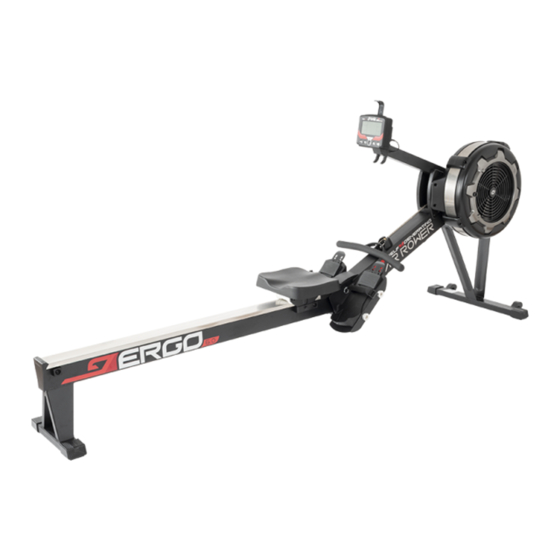
Summary of Contents for Orbit ERGO6.2
- Page 1 ERGO6.2 ERGO6.2 ERGO6.2 440 lbs/200 kgs.
- Page 2 440lbs/200kg. 20. This AIR ROWER is not intended for use by people, including children, with reduced physical, sensory, or mental capabili�es , or lack of experience and knowledge. Unless they have been given supervision or instruc�on concerning use of the of the product by a person who’s responsible for his/ her safety. 21.
-
Page 4: Equipment Warning, Caution Labels
EQUIPMENT WARNING, CAUTION LABELS This chart is provided to help identify the warning, caution, and notice labels on the ERGO6.1 AIR ROWER. Please take a moment to familiarize yourself with all of the warning, caution, and notice labels. Label is larger than actual size CAUTION LABEL... - Page 8 #81 M6X1X16mm 4PCS #76 M6 4PCS Allen Wrench 5mm A ach Front Support Leg A(7) and Front Support Leg B(8) to Main Frame(175) by using: 4 PCs of M6x16mm Socket Head Cap Screw(81) and M6 Flat Washer(76). #81 M6X1X16mm 4PCS #76 M6 4PCS Allen Wrench 5mm...
- Page 9 Li� up the Main Frame(175). Insert the Pedal Sha� 16mm(139) and Pedal Sha� 12mm(140) in sequence from le� Pedal Support Plate(177) to Main Frame(175) and then to right Pedal Support Plate(177). Tighten above parts by using: 2 PCs of M8x20mm Socket Head Cap Screw(173) and Foot Pedal End Cap(178). #173 M8X1.25X20mm 2PCS Allen Wrench 6mm 2PCS...
- Page 10 Li� up the Lower Console Monitor Post(135). A�ach the Lower Console Monitor Post(135) on Le�/ Right Side Cover(57/ 58) by using: 1 PC of M6x12mm Phillips Pan Head Screw(131). #131 M6X1X12mm 2PCS Screwdriver...
- Page 11 A�ach the Console Monitor(19) to the Console Moun�ng Bracket(179) by using: 1 PC of M8x75mm Bu�on Head Cap Screw(78), M8 Flat Washer(79), and M8 Nylon Lock Nut(80). Connect Sensor Cable(23) into the back of the Console Monitor(19a). #78 M8X1.25X75mm 1PCS #79 M8 1PCS #80 M8 1PCS Allen Wrench 6mm...
-
Page 13: Computer Instructions
COMPUTER INSTRUCTIONS Front View Back View Smartphone Holder Ba�eries Cover Sensor Cable Plugin Operates on 2 size C Your ROWER u�lizes an air fan system to create resistance for your workout. We recommend that you use this computer console to vary your workout from session to session and note your progress toward your fitness goals. - Page 14 COMPUTER INSTRUCTIONS Func�on Bu�ons BACK BUTTON: - When selec�ng the programs, press the bu�on to return to the previous program. - When you finish a running program, press the bu�on to jump into the IDEL mode. SELECT BUTTON: - In IDLE mode, press and release SELECT to cycle through each program op�on.
-
Page 15: Console Display
COMPUTER INSTRUCTIONS Console Display STROKE RATE - Display the current stroke per minute during exercise - The lightened up semi-circle equals to the TIME STROKE stroke rate that displayed in numbers. The - Total workout �me - Display the total number of more grids it shows, the higher your stroke strokes during exercise rate is. - Page 16 COMPUTER INSTRUCTIONS PROGRAMS The console monitor has 8 programs. Press SELECT to change workout programs according to the following sequence. Quick Start Program > Distance Countdown > Time Countdown > Calories Countdown > Game > 20/10 Interval > 10/20 Interval > 10/10 Customize Interval 1.
- Page 17 COMPUTER INSTRUCTIONS PROGRAMS The console monitor has 8 programs. Press SELECT to change workout programs according to the following sequence. Quick Start Program > Distance Countdown > Time Countdown > Calories Countdown > Game > 20/10 Interval > 10/20 Interval > 10/10 Customize Interval 5.
-
Page 18: Available Apps
COMPUTER INSTRUCTIONS Please make sure the console is ac�vated in order BLUETOOTH CONNECTION to proceed Bluetooth connec�on with your smart- phone or tablet devices. AVAILABLE APPS Kinomap D-fit ENTER SELECT BACK STOP FTMS PROTOCOL The “bt” will be displayed and switch between pulse when connec�ng to an app. - Page 19 The Handlebar (3) can be placed on the hook in the Upper Console Monitor Post(134), refer to illustra�on on A. Or, you can place the handlebar (3) on the Handlebar Holder(52) as shown in illustra�on on B.
- Page 20 Bulge...
- Page 21 CONSOLE MONITOR POST ADJUSTMENT Posi�on the Main Frame Assmebly (175) as shown in the illustra�on. Remove the Main Frame Cap (68) from the Main Frame (175). Slide out the Bo�om Cover (70) from the Main Frame (175).
- Page 22 Posi�on the Main Frame Assembly (175) as shown in the below illustra�on. Un-hook the Le� Bungee Cord Hook (12L) from the Main Frame (175). Make a mark on the Cord (38) to move the hook forward 2 inches. Refer to View 1 - View 3 to un-�e the Cord (38) from the Le� Bungee Cord Hook (12L) and move the hook forward 2 inches.
- Page 23 The Main Frame (175) and the Rail Frame (176) can be separated to minimize the unit size for storage. Remove the Pull Pin (98) from the Main Frame (175). Li� up the Min Frame (175) by holding one of the pedal straps and pull out the Rail Frame (176) to separate. Insert the Pull Pin (98) back to the hole in the Main Frame (175) for storage.
- Page 30 Phillips Pan Head Screw, M6x12mm Padel Sha�, 16mm Padel Sha�, 12mm Le� Joint Cover Right Joint Cover...
- Page 31 Console EVA Pad Smart Phone Holder EVA Pad Phillips Pan Head Self-Tripping Screw, ST4.2X35mm Socket Head Cap Screw, M8X20 Seat Carriage Cover Main Frame Rail Frame Pedal Support Plate Foot Pedal End Cap Console Moun�ng Bracket...


Need help?
Do you have a question about the ERGO6.2 and is the answer not in the manual?
Questions and answers