Advertisement
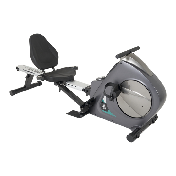
OWNER'S MANUAL
CAUTION:
Weight on this product should not exceed 300 LBS / 136 KGS
T6510
WARNING
Exercise can present a health risk.
Consult a physician before beginning
any exercise program with this
equipment. If you feel faint or dizzy,
immediately discontinue use of this
equipment. Serious bodily injury can
occur if this equipment is not assembled
and used correctly. Serious bodily injury
can also occur if all instructions are not
followed. Keep others and pets away
from equipment when in use. Always
make sure all bolts and nuts are
tightened prior to each use. Follow all
safety instructions in this manual.
MADE IN TAIWAN
Product May Vary Slightly
From Pictured.
v. VI
Advertisement
Table of Contents

Subscribe to Our Youtube Channel
Related Manuals for Orbit Hybrid Mag Trainer 2.0


Summary of Contents for Orbit Hybrid Mag Trainer 2.0
- Page 1 T6510 OWNER’S MANUAL WARNING Exercise can present a health risk. Consult a physician before beginning any exercise program with this equipment. If you feel faint or dizzy, immediately discontinue use of this equipment. Serious bodily injury can occur if this equipment is not assembled and used correctly.
-
Page 2: Safety Instructions
SAFETY INSTRUCTIONS WARNING: To reduce the risk of serious injury, read the following Safety Instructions before using the 3 in 1 Rower / Recumbent Bike & Pilates. Read all warnings posted on the 3 in 1 Rower / Recumbent Bike & Pilates. Read this Owner’s Manual and follow it carefully before using the 3 in 1 Rower / Recumbent Bike &... - Page 3 HAREWARE INDETIFICATION CHART This chart is provided to help identify the hardware used in the assembly process. Place the washers, the end of the bolts, or screws on the circles to check for the correct diameter. Use the small scale to check the length of the bolts and screws. NOTICE: The length of all bolts and screws except those with flat heads is measured from below the head to the end of the bolt or screw.
- Page 4 96 Bolt, Round Head (M6x1x30mm) 97 Bolt, Hex Head (M8x1.25x16mm) φ 109 Large Washer (M8x Allen Wrench (M6) Hex Wrench Combination Wrench...
- Page 5 ASSEMBLY INSTRUCTIONS Place all parts form the box in a cleared area and position them on the floor in front of you. Remove all packing materials from your area and place them back into the box. Do not dispose of the packing materials until assembly is completed.
- Page 6 ASSEMBLY INSTRUCTIONS STEP 5: a. Attach the SUPPORT BRACKET(60) onto the RAIL(52) with 4pcs HEX BOLTS (M8x16mm)(97). b. Press the NUT CAPS(79) onto the NYLOCK NUT(M10)(105) and the HEX BOLT(M10x75mm) (100). NOTE: 1pcs NYLOCK NUT(M10)(105) and 1pcs HEX BOLT(M10x75mm) (100) already fully secured on both side of the Support Tube (56).
- Page 7 ASSEMBLY INSTRUCTIONS NOTE: Be careful not to damage the PULSE SENSOR WIRES(73,74) while doing assembly STEP 9 to STEP 10. STEP 9: a. NOTE: 4pcs BUTTON HEAD BOLTS(M8x12mm)(114) will already be pre-attached on the SEAT HANDRAIL(70). b. Remove 4pcs BUTTON HEAD BOLTS(M8x12mm)(114) from the SEAT HANDRAIL(70).
- Page 8 ASSEMBLY INSTRUCTIONS NOTE: a. The RIGHT PEDAL(41) has R decal stamped on the end of the right pedal shaft. The RIGHT PEDAL(41) has right hand threads and is tightened by turning clockwise. b. The LEFT PEDAL(39) has L decal stamped on the end of the left pedal shaft.
-
Page 9: Operational Instructions
OPERATIONAL INSTRUCTIONS RECUMBENT BIKE MODE AND ROWER MODE Your 3 in 1 Rower, Recumbent Bike & Pilates can be used in the Recumbent Bike mode or the Rower mode. When the SPRING PIN(67) locks the SEAT ASSEMBLY to the RAIL(52), the 3 in 1 Rower, Recumbent Bike &... - Page 10 BODY MOVEMENT EXERCISE RECUMBENT EXERCISE BUTTOCKS EXERCISE Be sure to step on the iron PILATES PEDAL LEG EXTENSION EXERCISE LEG STRETCH EXERCISE Be sure to step on the iron PILATES PEDAL ROWER EXERCISE BICEP CURL EXERCISE Be sure to step on the iron PILATES PEDAL TRICEPPULL EXERCISE BACK &...
- Page 11 STORAGE 1. To store the 3 in 1 Rower, Recumbent Bike & Pilates simply keep it in a clean dry place. 2. To avoid damage to the electronics meter, remove the batteries before storing the 3 in 1 Rower, Recumbent Bike & Pilate for one year or more. 3.
-
Page 12: Power Off
“C ONSOLE NSTRUCTIONS” OWER a. Make sure the item’s adaptor is correctly plugged into the socket b. Rowing or pressing any keys to active the console. The console display will then light up with a short beep sound, indicating the console will be ready for OWER The console would automatically shut off after 4 minutes of inactivity... - Page 13 “C ONSOLE NSTRUCTIONS – ONSOLE UTTONS ” START\STOP a. Press to begin your exercise START\STOP b. Press again to stop and pause all functions during your exercise program. All the date on the display will then freeze. START\STOP c. Press again to resume the program and all the date displayed will continue until the program has finished.
- Page 14 “C ONSOLE NSTRUCTIONS”– ONSOLE UNCTIONS” MODE a. During workout, press button until “SCAN” shows on the screen. b. The console would scan automatically from TIME, SPM, COUNT, CAL in order at 5 second intervals Count Up: If a target time was not selected, TIME will count up from 0:00 to maximum 99:59 minutes Count Down: If you have set the target TIME (1:00 TO 99:00;...
- Page 15 “C ONSOLE NSTRUCTIONS”– ANUAL ROGRAM & 5” MANUAL PROGRAM P1 ROLLING PROGRAM P2 VALLEY PROGRAM P3 FAT BURN PROGRAM P4 RAMP PROGRAM P5 RANOM PROGRAM “1” Prior information: Press any button on the console or begin rowing to turn on the console Make sure that the power cord is properly plugged into the socket The console would automatically shut off after 4 minutes of inactivity Press any button on the console or begin rowing to turn on the console.
- Page 16 “C ONSOLE NSTRUCTIONS”– ANUAL ROGRAM & 5” “B. SET THE DESIRED TIME UP or DOWN button: MANUAL or PROGRAM (P1~P5) MODE After pressing the button to enter into , the TIME function mode will appear with the display flashing “0:00” UP or DOWN buttons to set the desired TIME (1:00 TO 99:00;...
- Page 17 “C ONSOLE NSTRUCTIONS”– ANUAL ROGRAM & 5” “F. SET THE TARGET HEART RATE/PULSE LIMIT UP or DOWN button: UP or DOWN buttons to set the desired TARGET HEART RATE/PULSE LIMIT (90 TO 220BPM (BEATS PER MINUTE); 1 BPM INCREMENT) NOTE: If there is no need to set the desired TARGET HEART RATE/PULSE LIMIT, press MODE button to finish all the setting function (TIME, COUNT, CAL, TARGE HEART RATE/PULSE LIMIT) value MODE...
-
Page 18: Troubleshooting
TROUBLE SHOOTING PROBLEM POSSIBLE CAUSE SOLUTION 1) Review the Assembly Instructions and check that all the Computer Plugs and Sockets are FIRMLY and correctly connected. 2) Review the Bike’s Magnetic Resistance System to ensure that it is set correctly and thy be at it can freely be adjusted. - Page 19 PROBLEM POSSIBLE CAUSE SOLUTION You have the wrong Check that the Batteries or the Adaptor Specifications coincide with Instruction Manual Adaptor or the wrong Specifications. Batteries? The Mains Power Check that the Mains Power is switched on and is indeed supplying power. switch is turned off? Check that the Adaptor is correctly connected to the Main Power Socket and is The LCD...
-
Page 20: Conditioning Guidelines
CONDITIONING GUIDELINES How you begin your exercise program depends on your physical condition. If you have been inactive for several years, or are severely overweight, you must slowly and increase your time on the item gradually: a few minutes per workout. Initially, you may be able to exercise only for a few minutes in your target zone, however, your aerobic fitness will improve over the next six to eight weeks. -
Page 21: Warm-Up And Cool-Down
WARM-UP and COOL-DOWN Warm-up The purpose of warming up is to prepare your body for exercise and to minimize injuries. Warm up for two to five minutes before strength-training or aerobic exercising. Perform activities that raise your heart rate and warm the working muscles. Activities may include brisk walking, jogging, jumping jacks, jump rope, and running in place. -
Page 23: Parts List
PARTS LIST PART NAME PART NAME Main Frame Right Cover Front Stabilizer Flange Bolt (M8x1.25x25mm) Axle Left Pedal Pulley Left Pedal Strap Strap Wheel Right Pedal Connection Wheel Right Pedal Strap One Way Bearing(3520) Stand Bearing (6004zz) Pedal Shaft C Ring (M20) Spacer Bearing Housing Foot Pedal... - Page 24 PART NAME PART NAME Pulse Sensor Wire 111 One way Bearing(2520) Pulse Coil Wire 113 Roller Spacer Pulse Connection Wire 114 Bolt, Button Head (M8x12mm) Moving Wheel 115 Bolt, Round Head (M5x12mm) Round Endcap (60mm) 116 Pilates Pedal Round Plug (25mm) 117 Plug Nut Cap (M10) 118 Bolt, Hex Head(M8x1.25x70mm)
Need help?
Do you have a question about the Hybrid Mag Trainer 2.0 and is the answer not in the manual?
Questions and answers