
Related Manuals for INOXPA OVERFLOW VALVE


Summary of Contents for INOXPA OVERFLOW VALVE
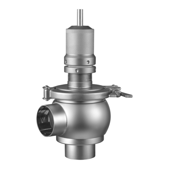
- Page 1 INSTALLATION, SERVICE AND MAINTENANCE INSTRUCTIONS OVERFLOW VALVE 74700 Original Instructions 10.207.30.07EN (0) 2023/11...
- Page 2 INOXPA S.A.U. Telers, 60 17820 - Banyoles (Spain) hereby declare under our sole responsibility that the VALVE Machine: OVERFLOW VALVE Model: 74700 Type: DN 25 - DN 80 / OD 1’’ - OD 3’’ Size: IXXXXXXXXX IXXXXXXXXX Serial number: XXXXXXXXXIINXXX...
- Page 3 INOXPA S.A.U. Telers, 60 17820 - Banyoles (Spain) hereby declare under our sole responsibility that the VALVE Machine: OVERFLOW VALVE Model: 74700 Type: DN 25 - DN 80 / OD 1’’ - OD 3’’ Size: IXXXXXXXXX IXXXXXXXXX Serial number: XXXXXXXXXIINXXX...
-
Page 4: Table Of Contents
..................................22 9.2. Materials ................................22 9.3. Sizes available ..............................22 9.4. Weights of overflow valve 74700 ........................ 22 9.5. Dimensions of the overflow valve 74700 ....................23 9.6. Dimensions of the overflow valve 74700 with handle ................23 9.7. Exploded drawing and parts list of the overflow valve 74700 ............24 9.8. Exploded drawing and parts list of the overflow valve 74700 with handle ........25 9.9. Exploded drawing and parts list of the overflow valve 74700 PTFE seat seal ......26 9.10. Exploded drawing and parts list of the overflow valve 74700 PTFE with handle and PTFE seat seal ..................................27 INOXPA S.A.U. 10.207.30.07EN · (0) 2023/11... -
Page 5: Generalities
Changing the service conditions can only be carried out with prior written authorization from INOXPA. The non-compliance of the prescribed indications in this manual means misuse of this gear on the technical side and the personal safety and this, exempt INOXPA of all responsibility in case of ac- cidents and personal injuries and/or property damage. Also, excluded from the warranty all break- downs caused by improper use of the gear. Please do not hesitate to contact us in case of doubts or if further explanations are required regar- ding specific data (adjustments, assembly, disassembly, etc.). INOXPA S.A.U. 10.207.30.07EN · (0) 2023/11... -
Page 6: Safety
Always take into account the Technical Specifications of chapter 9. NEVER disassemble or remove the valve until the pipes have been emptied. Bear in mind that the fluid in the pipe may be hazardous or extremely hot. Consult the regula- tions in effect in each country for these cases. Release the spring tension before starting the disassembly of the valve. Do not leave loose parts on the floor. INOXPA S.A.U. 10.207.30.07EN · (0) 2023/11... -
Page 7: General Information
The valve can incorporate a handle designed to allow the valve remains partially open. Thus, during the CIP process, the cleaning products can pass through the valve. 4.2. APPLICATION The overflow valve 74700 is a valve used to perform bypass as a relief measure to protect lines, pumps, accessories, tanks, etc. of the dairies, food, beverage, pharmaceutical or chemical indus- tries. INOXPA S.A.U. 10.207.30.07EN · (0) 2023/11... -
Page 8: Installation
The buyer or user shall be liable for assembly, installation, start-up and operation of the valve. Take all possible precautions when transport and storage the valve to avoid damage it and its com- ponents. 5.3. IDENTIFICATION OF THE VALVE Each valve is inscribed with its fabrication number. Indicate de fabrication number on all documents to refer to the valve. INOXPA S.A.U. 10.207.30.07EN · (0) 2023/11... - Page 9 DN 40 OD 1½’’ DN 50, OD 2’’ OD 2½’’ DN 65 OD 3’’ DN 80 Seals EPDM PTFE/FPM Material 1.4404 (AISI 316L) Connection welded/welded male/welded male/male clamp/clamp Standard pipe Type standard manual Product family Overflow valve 74700 INOXPA S.A.U. 10.207.30.07EN · (0) 2023/11...
-
Page 10: Location
In case of joining the valve to the pipe by fittings do not forget the seals and tighten the unions pro- perly. The overflow valve can be installed in any position although fitting it upside down is not recommen- ded. Recommended Not recommended During installation, the valve avoids using excessive force and pay special attention to: - vibrations that may be produced on the facility, - thermal dilation that the pipe may undergo when hot fluids are circulating, - the weight that the pipe can support, - excessive welding current. INOXPA S.A.U. 10.207.30.07EN · (0) 2023/11... -
Page 11: Checking And Review
25 - 1’’ 40 - 1½’’ 50 - 2’’ 65 - 2½’’ 80 - 3’’ - Mount the valve following the instructions indicated in chapter 8.5. Disassembly and assembly of the overflow valve 74700, 8.6. Disassembly and assembly of the overflow valve 74700 with handle and 8.7. Disassembly and assembly of the overflow valve 74700 with PTFE seat seal. INOXPA S.A.U. 10.207.30.07EN · (0) 2023/11... -
Page 12: Start-Up
Do not modify the operating parameters for which the valve has been designed without prior written authorisation from INOXPA. ¡Burn hazard! Do not touch the valve or the pipes when hot fluids are circulating or when cleaning and/or sterilization are being carried out. 6.1. CALIBRATION OF THE VALVE Upon request, the overflow valve is shipped calibrated from the factory. The valve calibration is performed with a flow recirculation through a bypass-type mounting. To per- form it, it is necessary to have a pump, a gauge, a shut-off valve and the overflow valve to tare and follow the next steps: - operate the pump with the shut-off valve in closed position. Thus, the flow will do the recircula- tion going through the overflow valve, - loosen the lock nut and tighten the top nut of the overflow valve until the gauge indicates the whished pressure in the overflow valve. Once the valve is calibrated, it will open when the installation pressure exceeds the calibrated pres- sure. So, the flow will recirculate to prevent the installation damage. INOXPA S.A.U. 10.207.30.07EN · (0) 2023/11... -
Page 13: Operating Problems
Shaft seal defective - Replace the seat seal with another of different • Deformation of seat seal quality if it has deteriorated prematurely • Spring in poor condition and/or jam for the dirt - Replace or clean the spring and the shaft The valve does not open when the pressure • - Calibrated the valve increases INOXPA S.A.U. 10.207.30.07EN · (0) 2023/11... -
Page 14: Maintenance
Use statistics for planning inspections. During assembly, apply lubricants that are suitable with the Lubrication material of which the seat seal is made. See the following table. NLGI DIN SEAL COMPONENT LUBRICANT 51818 Class klübersynth UH 1 64-2403 EPDM / FPM PARALIQ GTE 703 INOXPA S.A.U. 10.207.30.07EN · (0) 2023/11... -
Page 15: Cleaning
Check the concentration of the cleaning solutions. An incorrect concentrations may lead to the deterioration of the valve seals. To remove any traces of cleaning products, ALWAYS perform a final rinse with clean water at the end of the cleaning process. Clean the entire interior and exterior of the valve before starting disassembly and assem- bly tasks. 8.3.2. Automatic SIP (sterilization-in-place) Sterilization with steam is applied to all equipment including the pigging. ATTENTION Do NOT start the equipment during the sterilization with steam. The parts and the materials will not be damaged if the indications specified in this manual are observed. No cold fluid can enter the equipment until the temperature of the equipment is lower than 60°C (140°F). INOXPA S.A.U. 10.207.30.07EN · (0) 2023/11... - Page 16 Maintenance Maximum conditions during the SIP process with steam or superheated water: a. maximum temperature: 140ºC / 284ºF b. maximum time: 30 min c. cooling: sterile air or inter gas d. materials: EPDM (the material FPM is not recommended) INOXPA S.A.U. 10.207.30.07EN · (0) 2023/11...
-
Page 17: Disassembly And Assembly The Valve
The following tools are needed in order to disassembly and assembly the valve and the drives: - an spanner wrench to lose the locknut. 8.5. DISASSEMBLY AND ASSEMBLY OF THE OVERFLOW VALVE 74700 8.5.1. Disassembly Release the tension of the springs before loosening the clamp. - Page 18 Maintenance INOXPA S.A.U. 10.207.30.07EN · (0) 2023/11...
-
Page 19: Disassembly And Assembly Of The Overflow Valve 74700 With Handle
Maintenance 8.6. DISASSEMBLY AND ASSEMBLY OF THE OVERFLOW VALVE 74700 WITH HANDLE 8.6.1. Disassembly Release the tension of the springs before loosening the clamp. 1. Remove the pin (50A) from the handle (04). 2. Disassemble the handle (04) from the shaft (08). 3. If you want the same set value when you mount the valve, mark the part of the shaft (08) that pro- jects the top nut (26C) to sign its position. 4. Disassemble the top screw (22D). 5. Lose the lock nut (26F). 6. Unscrew and disassemble the top nut (26C) of the valve. 7. Unscrew and disassemble the lock nut (26F) of the valve. 8. Remove the clamp (34). - Page 20 Maintenance INOXPA S.A.U. 10.207.30.07EN · (0) 2023/11...
-
Page 21: Disassembly And Assembly Of The Overflow Valve 74700 With Ptfe Seat Seal
Maintenance 8.7. DISASSEMBLY AND ASSEMBLY OF THE OVERFLOW VALVE 74700 WITH PTFE SEAT SEAL Release the tension of the springs before loosening the clamp. Follow the same steps of chapter 8.5. 8.6. taking into account that in the case of valves with PTFE seat seals, the sleeve shaft carries an O-ring (20C) inside it. INOXPA S.A.U. 10.207.30.07EN · (0) 2023/11... -
Page 22: Technical Specifications
External surface finish matt 9.3. SIZES AVAILABLE DIN EN 10357 serie A DN 25 - DN 80 (formerly DIN 11850 serie 2) ASTM A269/270 OD 1’’ - OD 3’’ (corresponds to OD pipe) Connections weld, male, clamp 9.4. WEIGHTS OF OVERFLOW VALVE 74700 WEIGHT (kg) Valve with Standard valve handle 1’’ 1½’’ 2’’ 2½’’ 3’’ 1) connection weld/weld INOXPA S.A.U. -
Page 23: Dimensions Of The Overflow Valve 74700
Technical Specifications 9.5. DIMENSIONS OF THE OVERFLOW VALVE 74700 Dimensions ØB 1’’ 1½’’ 2’’ 2½’’ 3’’ 9.6. DIMENSIONS OF THE OVERFLOW VALVE 74700 WITH HANDLE Dimensions ØB 1’’ 1½’’ 2’’ 2½’’ 3’’ INOXPA S.A.U. 10.207.30.07EN · (0) 2023/11... -
Page 24: Exploded Drawing And Parts List Of The Overflow Valve 74700
Technical Specifications 9.7. EXPLODED DRAWING AND PARTS LIST OF THE OVERFLOW VALVE 74700 Position Description Quantity Material body 1.4404 (AISI 316L) shaft seal EPDM-FPM external spring 1.4310 (AISI 302) internal spring 1.4310 (AISI 302) shaft 1.4404 (AISI 316L) shaft sleeve 1.4404 (AISI 316L) guide bushint Iglidur G body cover 1.4404 (AISI 316L) spring cover 1.4307 (AISI 304L) -
Page 25: Exploded Drawing And Parts List Of The Overflow Valve 74700 With Handle
Technical Specifications 9.8. EXPLODED DRAWING AND PARTS LIST OF THE OVERFLOW VALVE 74700 WITH HANDLE Position Description Quantity Material body 1.4404 (AISI 316L) handle 1.4307 (AISI 304L) shaft seal EPDM-FPM spring 1.4310 (AISI 302) shaft 1.4404 (AISI 316L) shaft sleeve 1.4404 (AISI 316L) body cover 1.4404 (AISI 316L) spring cover 1.4307 (AISI 304L) flat seal EPDM - FPM... -
Page 26: Exploded Drawing And Parts List Of The Overflow Valve 74700 Ptfe Seat Seal
Technical Specifications 9.9. EXPLODED DRAWING AND PARTS LIST OF THE OVERFLOW VALVE 74700 PTFE SEAT SEAL Position Description Quantity Material body 1.4404 (AISI 316L) shaft seal external spring 1.4310 (AISI 302) internal spring 1.4310 (AISI 302) shaft 1.4404 (AISI 316L) shaft sleeve 1.4404 (AISI 316L) guide bushing Iglidur G body cover 1.4404 (AISI 316L) spring cover 1.4307 (AISI 304L) -
Page 27: Exploded Drawing And Parts List Of The Overflow Valve 74700 Ptfe With Handle And Ptfe Seat Seal
Technical Specifications 9.10. EXPLODED DRAWING AND PARTS LIST OF THE OVERFLOW VALVE 74700 WITH HANDLE AND PTFE SEAT SEAL Position Description Quantity Material body 1.4404 (AISI 316L) handle 1.4307 (AISI 304L) shaft seal spring 1.4310 (AISI 302) shaft 1.4404 (AISI 316L) shaft sleeve 1.4404 (AISI 316L) body cover 1.4404 (AISI 316L) spring cover 1.4307 (AISI 304L) - Page 28 How to contact INOXPA S.A.U.: Contact details for all countries are continaually updated on our website. Please visit www.inoxpa.com to access the information. INOXPA S.A.U. Telers, 60 - 17820 - Banyoles - Spain...
Need help?
Do you have a question about the OVERFLOW VALVE and is the answer not in the manual?
Questions and answers