Table of Contents
Advertisement
Quick Links
Advertisement
Table of Contents

Related Manuals for INOXPA INNOVA J


Summary of Contents for INOXPA INNOVA J
- Page 1 INSTALLATION, SERVICE AND MAINTENANCE INSTRUCTIONS SINGLE SEAT RELIEF VALVE INNOVA J INOXPA S.A.U. Telers, 60 Aptdo. 174 17820 – Banyoles Tel.: +34 972 57 52 00 Fax.: +34 972 57 55 02 inoxpa@inoxpa.com www.inoxpa.com Original Manual 10.245.30.01EN (0) 2018/05...
- Page 2 Hereby declare under our sole responsibility that the machine Relief Valve Designation INNOVA Type INNOVA J From serial number I282400 to I500000 / 000061900IIN to 000100000IIN Fulfills all the relevant provisions of the following directive: Machinery Directive 2006/42/CE Pressure Equipment Directive 2014/68/EU...
-
Page 3: Safety
The information published in this instruction manual is based on updated data. INOXPA reserves the right to modify this instruction manual without prior notice. 1.2. INSTRUCTIONS FOR START-UP This instruction manual contains essential and useful information for the correct handling and maintenance of your valve. - Page 4 1.4.5. Warranty Any warranty will be void immediately and lawfully; additionally, INOXPA shall be compensated for any civil liability claims submitted by third parties, in the following cases: The installation and maintenance work has not been carried out following the instructions in this ...
-
Page 5: Table Of Contents
7.6. Replacing the seat seal ......................19 7.7. Actuator assembly / disassembly....................20 8. Technical specifications ...................... 22 8.1. Technical specifications ......................22 8.2. Exploded drawing and parts list Innova J ................... 23 (0) 2018/05 2 . Table of contents... -
Page 6: General Information
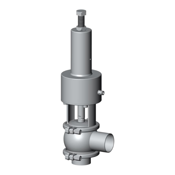
3. General information 3.1. DESCRIPTION INNOVA J (relief) valve is pneumatically actuated single-seat valve .Closing pressure of the valve is set by the spring pressure, which can be regulated by means of the screw located on the top of the valve. When the set pressure exceeds, valve opens. -
Page 7: Installation
Fabrication number 4.2. TRANSPORTATION AND STORAGE INOXPA shall in no case be liable for improper unpacking of the valve and its components. 4.2.1. Delivery Check to see whether all the parts listed on the delivery slip are present: Complete valve. -
Page 8: Identification
4.3. IDENTIFICATION Options ID Ra<0,5 Actuator T1 S/E NC T2 S/E NC T3 S/E NC T4 S/E NC Size DN 25, OD 1" DN 40, OD 1 1/2" DN 50, OD 2" OD 2 1/2" DN 65 OD 3" DN 80 DN 100, OD 4"... -
Page 9: Positioning
4.4. POSITIONING Position the valve in a way that facilitates inspections and reviews. Allow sufficient space around the valve for adequate review, dismantling and maintenance (see table in section 4.8.1. Single seat relief valve, weld/weld). 4.5. DIRECTION OF FLOW The following image indicates the recommended direction for product flow, as well as the direction of closing, depending on the type of valve. -
Page 10: Checking And Review
4.7. CHECKING AND REVIEW Perform the following checks before using: Check that the clamps and nuts are well secured. Open and close the valve (applying compressed air to the actuator) several times to make sure it operates correctly and to make sure that the shaft joint is coupled smoothly to the valve housing. 4.8. -
Page 11: Actuator Air Connection
Connect and check the compressed air connections. INOXPA valves are supplied with connections for Ø6 pipe, and with a silencer on S/E actuators. Consider the quality of the compressed air, according to the specifications described in 8. -
Page 12: Start-Up
5.3. OPERATION Do not modify the operating parameters for which the valve has been designed without prior written authorisations from INOXPA. Do not touch the moving parts of the coupling between the actuator and the valve when the actuator is connected to the compressed air supply. -
Page 13: Valve Setting
5.4. VALVE SETTING Type J valve can be set by client. Calibration requires a pump, a pressure gauge (to measure the pressure), a shut-off valve and Type J valve. Start up the pump with the shut-off valve in the closed position. The liquid will pass through the Type J valve, which will act as a bypass (recirculation). -
Page 14: Operating Problems
6. Operating problems Water hammer Valve does not open/close Internal leak of product (valve closed) The valve plug is sticking PROBABLE CAUSES SOLUTIONS Replace the seals Replace the seals with ones made of a different material or grade that is more appropriate for The seal or guide bushing is worn, deteriorated the product •... -
Page 15: Maintenance
7. Maintenance 7.1. GENERAL CONSIDERATIONS This valve, just like any other machine, requires maintenance. The instructions in this manual cover the identification and replacement of spare parts. The instructions are aimed at maintenance personnel and those responsible for the supply of spare parts. Carefully read chapter 8. -
Page 16: Cleaning
7.2.2. Storage Valves should be stored in an enclosed location under the following conditions: Temperature from 15ºC to 30ºC Ambient humidity < 60% Equipment MAY NOT be stored outside. 7.2.3. Spare parts To order spare parts, you must indicate the valve type and the position and description of the part, as found in chapter 8. -
Page 17: Assembly And Disassembly
7.3.2. Automatic SIP (Sterilization-in-Place) Sterilization with steam is applied to all equipment including the pigging. Do NOT start the equipment during the sterilization with steam. The parts/Materials will not be damaged if the indications specified in this manual are observed. No cold fluid can enter the equipment until the temperature of the equipment is lower than 60°C (140°F). -
Page 18: Disassembly/Assembly Of The Innova J
7.5. DISASSEMBLY/ASSEMBLY OF THE INNOVA J 7.5.1. Disassembly Loosen nut (26) and unscrew screw (22). Apply compressed air to the actuator (10A) so that the plug shaft (08) passes the open position. Loosen and separate the clamps (34). Separate the actuator (10) and bottom port (02) from the valve housing (01). -
Page 19: Replacing The Seat Seal
7.6. REPLACING THE SEAT SEAL Put the plug shaft in a vertical position—for example, with a bench clamp—so that the shaft is kept stable and no damage is caused to the mating surface of the conical seal. Do not press the shaft too much if using a bench clamp. -
Page 20: Actuator Assembly / Disassembly
7.7. ACTUATOR ASSEMBLY / DISASSEMBLY Do not apply compressed air until the disassembly/assembly process is completed. The figure is a schematic representation of some of the steps in the actuator disassembly process. 7.7.1. Disassembly Fully loosen regulating screw (22) to remove nut (26) and regulating screw (22). - Page 21 7.7.3. Configuración del actuador The standard configuration of the valves is NC (Normally Closed). The following tools are needed to disassemble the actuator: Allen spanner 5mm (DN-25/40) 6mm (DN-50/80) 10mm (DN-100). Fine point screwdriver (to remove the snap ring). ...
-
Page 22: Technical Specifications
8. Technical specifications 8.1. TECHNICAL SPECIFICATIONS Valve Maximum working pressure 10 bar Maximum opening pressure 6 bar Minimum working pressure Vacuum Maximum working temperature 121ºC (250ºF) Standard seals EPDM (for higher temperatures, other grades of seals will be used) Actuator Compressed air pressure 6-8 bar Compressed air quality... -
Page 23: Exploded Drawing And Parts List Innova J
8.2. EXPLODED DRAWING AND PARTS LIST INNOVA J 8.2.1. Exploded drawing (0) 2018/05 8 . Technical specifications... - Page 24 8.2.2. Parts list Quantity Description Item Material Intermediate housing AISI 316L Bottom port AISI 316L Shaft seal EPDM / FPM / HNBR Flat seal EPDM / FPM / HNBR Valve shaft AISI 316L Actuator AISI 304 Housing cap (upper bushing) AISI 316L Housing cap (bottom bushing) AISI 316L...
- Page 25 NOTES...
- Page 26 NOTES...
- Page 27 NOTES...
- Page 28 Como ponerse en contacto con INOXPA S.A.U Los detalles de todos los países estan continuamente actualizados en nuestra página web. Visite www.inoxpa.com para acceder a la información...
Need help?
Do you have a question about the INNOVA J and is the answer not in the manual?
Questions and answers