Table of Contents
Advertisement
Quick Links
Advertisement
Table of Contents

Related Manuals for INOXPA C-TOP


Summary of Contents for INOXPA C-TOP
- Page 1 INSTALLATION, SERVICE AND MAINTENANCE INSTRUCTIONS C-TOP control head INOXPA, S.A. c/Telers, 54 Aptdo. 174 E-17820 Banyoles Girona (Spain) Tel. : (34) 972 - 57 52 00 Fax. : (34) 972 - 57 55 02 Email: inoxpa@inoxpa.com www.inoxpa.com Original Manual 10.420.30.00EN_RevB...
- Page 2 DECLARATION OF CONFORMITY INOXPA, S.A. Manufacturer: C/ Telers, 54 17820 Banyoles (Girona) - SPAIN Hereby declares, that the product: CONTROL HEAD C-TOP Name Type conforms to the specifications of the Council Directive: Low Voltage Directive 2006/95/EC (what repeal 73/23/CEE Directive), and are...
-
Page 3: Safety
Your must always bear in mind the set forth in Chapter 8. The installation and use of the C-TOP control head must always be carried out in accordance with health and safety rules that are to be applied. Before putting the valve / actuator into operation, check to make sure that it has been correctly assembled and that the shaft has been perfectly aligned. -
Page 4: Guarantee
• The repairs have not been carried out either by a member of our staff, or have been done without our company having issued prior written authorisation. • The parts used are not original INOXPA pieces. • Modifications have been carried out without prior written consent. -
Page 5: Table Of Contents
4.7. As-interface electric connection ..................11 4.8. Pneumatic connections ....................14 Commissioning 5.1. Comissioning ......................... 15 5.2. C-TOP commissioning ..................... 15 Troubleshooting: Causes and solutions Maintenance 7.1. General comments ......................17 7.2. Storage ......................... 17 ... -
Page 6: General Information
3.2. OPERATING PRINCIPLE The C-TOP is a control head that includes signalling and command devices to control all types of (piston) process valves. This element incorporates the following functions in a single element: •... -
Page 7: Reception And Installation
NEW INSTALLATIONS: • INOXPA process valves. No adapter is required: the head is fitted directly on the upper part of the valve drive. • in valves made by other manufacturers. Easy fitting, all you need to do is to fit an adaptation bracket (See Figure 4.1). - Page 8 For microswitches. C-TOP 95691 REPAIR / REPLACING OLD MODELS: • replacing INOXPA '94 head. Order the SCV1010 assembly kit (for actuators and butterfly/ball check valve) or kit SCN1010 (for multi-way valves) along with the head. • replacing the Bürkert-model head. Order the SCV1011 assembly kit (for actuators and butterfly/ball check valve) or kit SCN1011 (for multi-way valves) along with the head.
-
Page 9: Fitting The Head
Figure 4.4 INOXPA is not liable for the improper unpacking of the control head and its components. Proceed with due care. Failure to do so may result in personal injuries. The assembly and stripping of the control head must only be carried out by qualified personnel. - Page 10 4.5.2. Wiring the head Connect the ø6 Fit the electric mm. pipes for the wiring, in the basic air to the C version and connect pneumatic (See the C connections 4.7 electrically. (See electrical connections 4.6 Check to make sure that the wire guide is good and tight.
-
Page 11: Electrical Connection
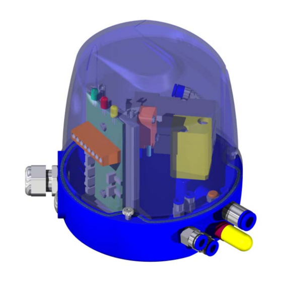
4.6.2 Electrical components All the electrical components used in the C-TOP head have a built-in pluggable connector which avoids having to carry out any further interventions or wiring. The printed wiring board has, as a standard feature, the capacity to plug in up to 3 solenoid valves (V1, V2, V3) and 3 proximity detectors or microswitches (S1, S2, S3). - Page 12 Solenoid 1 Inlet 1 Switch 1 n.c. Program: By default the direction is O, easily reprogrammable by master. This card is standard for the following heads: DESCRIPTION CODE C-TOP DETECTORES 24V DC 3+1E 3+1D V9721-4484001AS 4.Reception and Installation ED. 2010/11...
- Page 13 Inlet 1 Switch 1 n.c. This card is standard for the following heads: DESCRIPTION CODE C-TOP DETECTORES 24V DC 2E 3D AS-I V9721-2384001AS C-TOP DETECTORES 24V DC 3E 2D AS-I V9721-3284001AS C-TOP DETECTORES 24V DC 3E 3D AS-I V9721-3384001AS ED. 2010/11...
-
Page 14: Pneumatic Connections
Solenoid 1 Inlet 1 Switch 1 This card is standard for the following heads: DESCRIPTION CODE C-TOP DETECTORES 24V DC 0E 2D AS-I V9721-0284001AS C-TOP DETECTORES 24V DC 1E 1D AS-I V9721-1184001AS C-TOP DETECTORES 24V DC 1E 2D AS-I V9721-1284001AS... -
Page 15: Commissioning
They are supplied with M12 AS-i (Vampire) connector (2 meters long) that allow for an easy connection to the cable. All the C-TOP AS-i control units are by default supplied with the same direction (0), and each unit of the installation must be redirected from the Master. -
Page 16: Troubleshooting: Causes And Solutions
6. Troubleshooting: Causes and solutions PROBLEM CAUSE/EFECT SOLUTION • Check that the compressed air circuit bypass valve is open. Insufficient air supply • Check the supply pressure. • Insufficient flow. • Check the compressed air feed THE VALVE IS pressure. JERKING The actuator is not driving the valve efficiently. -
Page 17: Maintenance
7.4. ASSEMBLY AND STRIPPING INOXPA is not liable for the improper handling of the head control, or of its components. Before starting work on stripping the equipment, disconnect the actuator air and the head from the mains. -
Page 18: Technical Specifications
8. Technical Specifications 8.1. TECHNICAL SPECIFICATIONS MATERIALS Base PPO + GF, blue Cover PC, transparent, blue-grey Seals EPDM Weight 560 – 640 gr. PNEUMATIC SPECIFICATIONS Connections Air inlet: G 1/8" – is supplied with snap-fit plug for 6/4 pipe Air vent: G 1/8"... -
Page 19: Characteristics
8.2. CHARACTERISTICS solenoid Connection num. Detectors ( ) Voltage Description CODE valves V9721-0284000 V9721-1284000 2 proximity detectors 24V DC V9721-2284000 Control head with printed circuit board. V9721-3284000 Connectors Power is supplied directly to the V9621-0284000 connectors. M16 cable gland. V9621-1284000 24V DC 2 microswitches V9621-2284000... -
Page 20: Exploded View And Parts List
8.4. EXPLODED VIEW AND PARTS LIST with 2 proximity detectors and 1 solenoid valve (connector electrical connections) 24/110/220V AC/DC POSITION NAME MATERIAL QUANTITY Bull plug stainless Bull plug plastic Cover Base PPO + GF Block Aluminium Solenoid valve 3/2 Aluminium Cable gland M16 plastic Blank plate... - Page 21 with 2 proximity detectors and 2 solenoid valves (connector electrical connections) 24/110/220V AC/DC POSITION NAME MATERIAL QUANTITY Bull plug stainless Bull plug plastic Cover Base PPO + GF Block Aluminium Solenoid valve 3/2 Aluminium Cable gland plastic Blank plate M16 Aluminium φ4 polyethylene pipe Air coupling - straight...
- Page 22 In addition to our branches, INOXPA has a network of independent distributors that covers over 50 countries worldwide. For further information visit our web page. www.inoxpa.com The information is for guidance only. We reserve the right to change any material or characteristic without prior notice.
Need help?
Do you have a question about the C-TOP and is the answer not in the manual?
Questions and answers