Table of Contents
Advertisement
Quick Links
INSTALLATION, SERVICE AND
MAINTENANCE INSTRUCTIONS
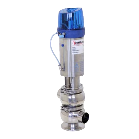
SINGLE-SEAT VALVE
INOXPA, S.A.
c/Telers, 54 Aptdo. 174
E-17820 Banyoles
Girona (Spain)
Tel. : (34) 972 - 57 52 00
Fax. : (34) 972 - 57 55 02
Email: inoxpa@inoxpa.com
www.inoxpa.com
Original Manual's Translation
10.210.30.00EN_RevC
ED. 2009/11
www.sks-online.com
www.sks-webshop.com
Advertisement
Table of Contents

Subscribe to Our Youtube Channel
Related Manuals for INOXPA NL


Summary of Contents for INOXPA NL
- Page 1 INSTALLATION, SERVICE AND MAINTENANCE INSTRUCTIONS SINGLE-SEAT VALVE INOXPA, S.A. c/Telers, 54 Aptdo. 174 E-17820 Banyoles Girona (Spain) Tel. : (34) 972 - 57 52 00 Fax. : (34) 972 - 57 55 02 Email: inoxpa@inoxpa.com www.inoxpa.com Original Manual’s Translation 10.210.30.00EN_RevC ED.
- Page 2 DECLARATION OF CONFORMITY (according to Directive 98/37/CE, annex II, part A) INOXPA, S.A Manufacturer: C/ Telers, 54 17820 Banyoles (Girona) - SPAIN Hereby declares, that the product: VALVE SINGLE SEAT – N/K/M 2009 Year of Name Type manufacture conforms to the specifications of the Council Directive:...
-
Page 3: Safety
Commitment to safety at the workplace. Protective goggles requirement. 1.4. GENERAL SAFETY INSTRUCTIONS. Read the instruction manual carefully before installing and starting up the valve. Contact INOXPA in case of doubt. 1.4.1. During the installation. Technical Specifications of Chapter 8 should always be observed. -
Page 4: Guarantee
• The repairs are not carried out by our personnel or have been carried out without our written authorisation. • The parts used are not INOXPA genuine parts. • Modifications have been carried out on our materials without written authorisation. -
Page 5: Table Of Contents
6.3. Cleaning ........................14 Assembly and disassembly 7.1. DISASSEMBLY / ASSEMBLY OF THE SINGLE-SEAT VALVE (NL/NT TYPE) ......15 7.2. DISASSEMBLY / ASSEMBLY OF THE SINGLE-SEAT VALVE (NL/NT TYPE) ......16 7.3. DISASSEMBLY / ASSEMBLY OF THE SINGLE-SEAT VALVE (NLFI TYPE) ......17 ... -
Page 6: Receiving And Installing
The first thing to do on receiving the valve is to verify that it is matches the delivery note. INOXPA will inspect all the equipment before packing, although it cannot guarantee that the merchandise will arrive intact to the user. For this reason, the valve received and any other article should be checked and, if it is found not to be in good condition and/or not all parts are included, the carrier should submit a report as soon as possible. -
Page 7: Location
The buyer or user will be responsible for the assembly, installation, starting and operation of the valve. 3.4. LOCATION. Place the valve in such a way as to facilitate inspections and checks. Leave sufficient space around the valve for appropriate inspection, separation and maintenance (See Section 3.8.1) 3.5. -
Page 8: Assembly
3.6. ASSEMBLY. Once the location of the valve is defined, the pipe can be connected by welding the bodies of the valve or by means of accessories (connectors). In this case, do not forget the seals and to tighten the joints well. In K, M, and N-type (two bodies) valves, it is advisable to use connection adapters to connect one of the bodies in order to facilitate disassembly of the valve. -
Page 9: Welding
3.8. WELDING. The welding work can only be carried out by persons qualified, trained and equipped with the necessary means to carry out this work. Disassemble the valve before starting the welding work. 3.8.1. Weld / weld single-seat valve. Fig. N/K/M Assembly and disassembly •... -
Page 10: Air Connection To Actuator
Connect and check the air connections as required; dual effect or single effect • INOXPA valves are supplied with Ø6 tube connections and a silencer in S/E actuators. • Mind the quality of the compressed air according to the specifications described in chapter 8 Technical Specifications. -
Page 11: Start-Up
4.3. OPERATION. Do not modify the operating parameters for which the valve has been designed without written prior authorisation from INOXPA. Do not touch the moving parts of the coupling between the actuator and the valve when the actuator is connected to the compressed air. -
Page 12: Operating Problems. Causes And Solutions
5. Operating problems. Causes and solutions. PROBLEM CAUSE/EFFECT SOLUTION • Replace the seals. • Replace the seals with others of different material and more appropriate to the product. The seal or bushing have worn out, deteriorated, or become blocked up. •... -
Page 13: Maintenance
6. Maintenance 6.1. GENERAL INFORMATION This valve, just like any other machine, requires maintenance. The instructions contained in this manual cover the identification and replacement of spare parts. The instructions have been prepared for maintenance personnel and for those responsible for the supply of spare parts. -
Page 14: Cleaning
6.2.3. Spare parts To request spare parts, it is necessary to indicate the type of valve, the position and the description of the part which can be Technical specifications found in the chapter. 6.3. CLEANING The use of aggressive cleaning products such as caustic soda and nitric acid may cause burns to the skin. -
Page 15: Assembly And Disassembly
Never disassemble the valve clamps directly without reading the instructions thoroughly. Assembly and disassembly of the valves / actuator must only be carried out by qualified staff. 7.1. DISASSEMBLY / ASSEMBLY OF THE SINGLE-SEAT VALVE (NL/NT TYPE) Disassembly Apply compressed air to the actuator (10) in order to set the plug (08) in the open position. -
Page 16: Disassembly / Assembly Of The Single-Seat Valve (Nl/Nt Type)
Never disassemble the valve clamps directly without reading the instructions thoroughly. Assembly and disassembly of the valves / actuator must only be carried out by qualified staff. 7.2. DISASSEMBLY / ASSEMBLY OF THE SINGLE-SEAT VALVE (NL/NT TYPE) Disassembly Operate the handle (04) in order to set the plug shaft (08) in the open position. -
Page 17: Disassembly / Assembly Of The Single-Seat Valve (Nlfi Type)
Proceed with caution. There is danger of personal injury. Always disconnect the compressed air before starting valve disassembly. Never disassemble the valve clamps directly without reading the instructions thoroughly. Assembly and disassembly of the valves / actuator must only be carried out by qualified staff. 7.3. -
Page 18: Disassembly / Assembly Of The Single-Seat Valve (Nlfm Type)
Proceed with caution. There is danger of personal injury. Always disconnect the compressed air before starting valve disassembly. Never disassemble the valve clamps directly without reading the instructions thoroughly. Assembly and disassembly of the valves / actuator must only be carried out by qualified staff. 7.4. -
Page 19: Disassembly / Assembly Of The Single-Seat Valve (K/M Type)
Proceed with caution. There is danger of personal injury. Always disconnect the compressed air before starting valve disassembly. Never disassemble the valve clamps directly without reading the instructions thoroughly. Assembly and disassembly of the valves / actuator must only be carried out by qualified staff. 7.5. -
Page 20: Disassembly / Assembly Of The Manual Single-Seat Valve (K/M Type)
Proceed with caution. There is danger of personal injury. Never disassemble the valve clamps directly without reading the instructions thoroughly. Assembly and disassembly of the valves / actuator must only be carried out by qualified staff. 7.6. DISASSEMBLY / ASSEMBLY OF THE MANUAL SINGLE-SEAT VALVE (K/M TYPE) Disassembly Operate the handle (04) in order to set the plug shaft (08) in the open... -
Page 21: Disassembly / Assembly Of The Actuator
Proceed with caution. There is danger of personal injury. Always disconnect the compressed air before starting valve disassembly. Never disassemble the valve clamps directly without reading the instructions thoroughly. Assembly and disassembly of the valves / actuator must only be carried out by qualified staff. 7.7. -
Page 22: Technical Specifications
8. Technical specifications VALVE GENERAL DATA DN-25 / 100 Maximum working pressure 10 bar DN-1"/4" Minimum working pressure Vacuum 121ºC (250ºF) EPDM standard seals Maximum working temperature (Other qualities of seals will be adapted for higher temperatures) Compressed air pressure 6-8 bar According to DIN/ISO 8573.1 Solid particle content: Quality class 3 / Particle size... -
Page 23: Single-Seat Valve Dimensions
8.1 SINGLE-SEAT VALVE DIMENSIONS. Fig. NL/NT KH/KE/KF/KG MD/MA/MB/MC – ND/NA/NB/NC Macho–Male Tuerca-Nut Clamp DIN 21,5 Macho-Male Tuerca-Nut Clamp OD 1” 1½” 2” 2½” 3” 4” ED. 2009/11 8. Technical specifications www.sks-online.com www.sks-webshop.com... -
Page 24: Manual-Operation Single-Seat Valve Dimensions
8.2 MANUAL-OPERATION SINGLE-SEAT VALVE DIMENSIONS Fig. NL/NT KH/KE/KF/KG MD/MA/MB/MC – ND/NA/NB/NC Macho–Male Tuerca-Nut Clamp DIN 21,5 Macho-Male Tuerca-Nut Clamp OD 1” 1½” 2” 2½” 3” 4” 8. Technical specifications ED. 2009/11 www.sks-online.com www.sks-webshop.com... - Page 25 Fig. NLFI Welding 1” 1½” 2” 2½” 3” 1” 1½” 2” 2½” 3” 4” Fig. NLFM Welding ED. 2009/11 8. Technical specifications www.sks-online.com www.sks-webshop.com...
-
Page 26: Section And Parts List
8.3 SECTION AND PARTS LIST. 8.3.1 Section and parts list FIG. NL/NT PNEUMATIC OPERATION • Fig. NL/NT Pneumatic Operation POSITION DESIGNATION MATERIAL QUANTITY Lower body L/T AISI 316L Shaft seal EPDM Valve shaft AISI 316L Actuator AISI 304 Guide bushing... - Page 27 8.3.3 Section and parts list FIG. NL/NT MANUAL OPERATION • Fig. NL/NT Manual Operation POSITIO DESIGNATION MATERIAL QUANTITY Lower body L/T AISI 316L Handle AISI 304 Shaft seal EPDM Valve shaft AISI 316L Guide bushing PTFE Body cap AISI 316L...
- Page 28 8.3.5 Section and parts list FIG. NLFI MANUAL OPERATION • Fig. NLFI Manual Operation POSITION DESIGNATION MATERIAL QUANTITY Lower body L/T AISI 316L Handle AISI 304 Shaft seal EPDM Valve shaft AISI 316L Guide bushing PTFE Body cap AISI 316L O-ring EPDM O-ring...
- Page 29 8.3.7 Section and parts list FIG. KH/KE/KF/KG PNEUMATIC OPERATION • Fig. KE/KF/KG/KH Pneumatic Operation POSITION DESIGNATION MATERIAL QUANTITY Lower body L/T AISI 316L Upper body L/T AISI 316L Shaft seal EPDM Valve shaft AISI 316L Actuator AISI 304 Guide bushing PTFE Body cap AISI 316L...
- Page 30 8.3.9 Section and parts list FIG. KH/KE/KF/KG MANUAL OPERATION • Fig. KE/KF/KG/KH Manual Operating POSICIÓN DESIGNACIÓN MATERIAL CANTIDAD Lower body L/T AISI 316L Upper body L/T AISI 316L Handle AISI 304 Shaft seal EPDM Valve shaft AISI 316L Guide bushing PTFE Body cap AISI 316L...
- Page 31 8.3.11 Section and parts list FIG. NA/NB/NC/ND PNEUMATIC OPERATION • Fig. NA/NB/NC/ND Pneumatic Operating POSITION DESIGNATION MATERIAL QUANTITY Lower body L/T AISI 316L Upper body L/T AISI 316L Blind lower opening AISI 316L Shaft seal EPDM Valve shaft AISI 316L Actuator AISI 304 Guide bushing...
- Page 32 8.3.13 Section and parts list FIG. NA/NB/NC/ND MANUAL OPERATION POSITION DESIGNATION MATERIAL QUANTITY Lower body L/T AISI 316L Upper body L/T AISI 316L Blind lower opening AISI 316L Handle AISI 304 Shaft seal EPDM Valve shaft AISI 316L Guide bushing PTFE Body cap AISI 316L...
- Page 33 8.3.15 Section and parts list FIG. MA/MB/MC/MD PNEUMATIC OPERATION POSITION DESIGNATION MATERIAL QUANTITY Lower body L/T AISI 316L Upper body L/T AISI 316L Blind lower opening AISI 316L Shaft seal EPDM Valve shaft AISI 316L Actuator AISI 304 Guide bushing PTFE Body cap AISI 316L...
- Page 34 8.3.17 Section and parts list FIG. MA/MB/MC/MD MANUAL OPERATION POSITION DESIGNATION MATERIAL QUANTITY Lower body L/T AISI 316L Upper body L/T AISI 316L Blind lower opening AISI 316L Handle AISI 304 Shaft seal EPDM Valve shaft AISI 316L Guide bushing PTFE Body cap AISI 316L...
- Page 35 8.3.19 Sealing kit list for PNEUMATIC OPERATION DESIGNATION EPDM Sealing Kit KE-N025 KE-N040 KE-N050 KE-N065 KE-N080 KE-N100 Type NL/NT VITON Sealing Kit KV-N025 KV-N040 KV-N050 KV-N065 KV-N080 KV-N100 Type NL/NT EPDM Sealing Kit KE-K025 KE-K040 KE-K050 KE-K065 KE-K080 KE-K100 Type KE/KF/KG/KH...
- Page 36 SAINT PETERSBURG Тel/Fax: 78126221626/78126221926 e-mail: spb@inoxpa.com In addition to our branch offices, INOXPA operates with an independent distributor network which encompasses a total of more than 50 www.inoxpa.com countries throughout the world. For more information, please, consult our web page: Orientative information.
Need help?
Do you have a question about the NL and is the answer not in the manual?
Questions and answers