Table of Contents
Advertisement
Quick Links
INSTALLATION, SERVICE AND MAINTENANCE
ANNEX FOR EC ATEX REGISTERED EQUIPMENT UNDER
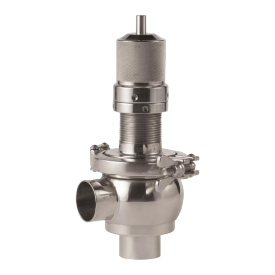
Ex OVERFLOW VALVE
The contents of this Annex complements the information included in the
instruction manual. The instructions of this Annex must be observed
whenever equipment registered under Directive 2014/34/EU is used.
If applicable, this Annex will be complemented with the manuals of the
ATEX registered components that form part of the assembly (e.g., seals,
etc.).
INSTRUCTIONS
DIRECTIVE 2014/34/EU:
1
Original Manual
10.207.30.01EN
(A) 2022/11
Advertisement
Table of Contents

Related Manuals for INOXPA OVERFLOW


Summary of Contents for INOXPA OVERFLOW
- Page 1 INSTRUCTIONS ANNEX FOR EC ATEX REGISTERED EQUIPMENT UNDER DIRECTIVE 2014/34/EU: Ex OVERFLOW VALVE The contents of this Annex complements the information included in the instruction manual. The instructions of this Annex must be observed whenever equipment registered under Directive 2014/34/EU is used.
- Page 2 10.207.30.06EN (0) 2022/11 EU Declaration of Conformity ATEX 2014/34/EU INOXPA, S.A.U. Telers, 60 17820 – Banyoles (Girona) Hereby declare under our sole responsibility that the machine VALVE Model OVERFLOW From serial number IXXXXXXXXX IXXXXXXXXX Fulfills all the relevant provisions of Safety and Health from ATEX 2014/34/EU Directive and...
-
Page 3: Instructions Manual
The limits of the operating conditions in explosive atmospheres must not be exceeded This valve was selected according to the operating conditions specified by the user. Therefore, INOXPA disclaims liability for any damage caused by the use of the valve under conditions other that those set forth in the order 1.4.3. -
Page 4: Guarantee
- The material has been badly used or has not been used according to the operating conditions in the classified area, operating in a different classified area, temperature or pressure conditions, and/or with a different substance. _______________________________________________________________________________________________ ED. 11/2022 1. SAFETY OVERFLOW VALVE... -
Page 5: Table Of Contents
7.2. Disassembly / Assembly of the overflow valve fig: 74700M 7.3. Disassembly / Assembly of the overflow valve with PTFE seat 7.4. Disassembly / Assembly of the overflow valve fig: 74700M with PTFE seat 8. Technical Specifications 8.1. Overflow valve dimensions 8.2. -
Page 6: Receiving And Installation
3.5. FLOW DIRECTION 3.6. OVERFLOW VALVE POSITION 3.7. ASSEMBLY To reduce the risk of static electricity, the assembly must be earthed to ensure electrical continuity between the pipes and the valve _______________________________________________________________________________________________ ED. 11/2022 3. RECEIVING AND INSTALLATION OVERFLOW VALVE... -
Page 7: Inspecting And Checking
It is strongly recommended that this type of work be carried out in non-classified atmospheres (i.e. there must not be an explosive atmosphere in the location of the valve when it is being handled) 3.9.1. Welding/welding overflow valve. Fig. 74700. _______________________________________________________________________________________________ ED. 11/2022... -
Page 8: Start-Up
INOXPA The valve was selected for specific working conditions in potentially explosive atmospheres at the time the order was placed. INOXPA will not be responsible for any damage which may be caused if the information provided by the buyer is incomplete or incorrect (type of liquid, viscosity, classification of the potentially explosive zone, gas generated by the potentially explosive atmosphere, etc.) -
Page 9: Maintenance
ATEX area, and must state the characteristics of that area. Otherwise, INOXPA cannot ensure that the valve operates with parts that are suitable for the classified area within which it is installed. -
Page 10: Assembly And Disassembly
7.1. DISASSEMBLY / ASSEMBLY OF THE OVERFLOW VALVE FIG: 74700 7.2. DISASSEMBLY / ASSEMBLY OF THE OVERFLOW VALVE FIG: 74700M 7.3. DISASSEMBLY / ASSEMBLY OF THE OVERFLOW VALVE WITH PTFE SEAT FIG: 7.4. DISASSEMBLY / ASSEMBLY OF THE OVERFLOW VALVE FIG: 74700M WITH PTFE... -
Page 11: Technical Specifications
_____________________________________________________________________________________ 8. Technical Specifications Temperature range. See section 3.3. 8.1. RELIEF VALVE DIMENSIONS 8.2. SECTION AND PARTS LIST _______________________________________________________________________________________________ ED. 11/2022 8. TECHNICAL SPECIFICATIONS OVERFLOW VALVE...
Need help?
Do you have a question about the OVERFLOW and is the answer not in the manual?
Questions and answers