
Related Manuals for INOXPA C-TOP Reed


Summary of Contents for INOXPA C-TOP Reed
- Page 1 INSTALLATION, SERVICE AND MAINTENANCE INSTRUCTIONS CONTROL HEAD Original Instructions 10.427.30.01EN (0) 2022/06...
- Page 2 17820 - Banyoles (Spain) hereby declare under our sole responsibility that the CONTROL HEAD Machine: C-TOP Reed Model: C-TOP Reed 24V DC 0E Type: C-TOP Reed 24V DC 1E C-TOP Reed 24V DC 2E C-TOP Reed 24V DC 3E IXXXXXXXXX...
- Page 3 17820 - Banyoles (Spain) hereby declare under our sole responsibility that the CONTROL HEAD Machine: C-TOP Reed Model: C-TOP Reed 24V DC 0E Type: C-TOP Reed 24V DC 1E C-TOP Reed 24V DC 2E C-TOP Reed 24V DC 3E IXXXXXXXXX...
-
Page 4: Table Of Contents
1. Table of Contents 1. Table of Contents 2. Generalities 2.1. Instructions manual ..........................5 2.2. Compliance with the instructions ......................5 2.3. Warranty..............................5 3. Security 3.1. Warning symbols............................. 6 3.2. General safety instructions ........................6 4. General Information 4.1. -
Page 5: Generalities
The information published in the instruction manual is based on updated data. INOXPA reserves the right to modify this instruction manual without prior notice. 2.2. COMPLIANCE WITH THE INSTRUCTIONS Not following the instructions may impose a risk for the operators, the environment and the machine, and may cause the loss of the right to claim damages. -
Page 6: Security
Observe the general requirements for PELV circuits in accordance with IEC/DIN EN 60204-1. Installation errors can damage the electronics or cause malfunctions. The C-TOP Reed contains electrostatically sensitive components. Electrostatic dischar- ge caused by improper handling or incorrect earthing can damage the internal electro- nics. - Page 7 Security All the electrical work should be carried out by specialised personnel. The C-TOP Reed contains electrostatically sensitive components. Electrostatic dischar- ge caused by improper handling or incorrect earthing can damage the internal electro- nics. 3.2.3. During maintenance Always take into account the Technical Specifications in chapter 8.
-
Page 8: General Information
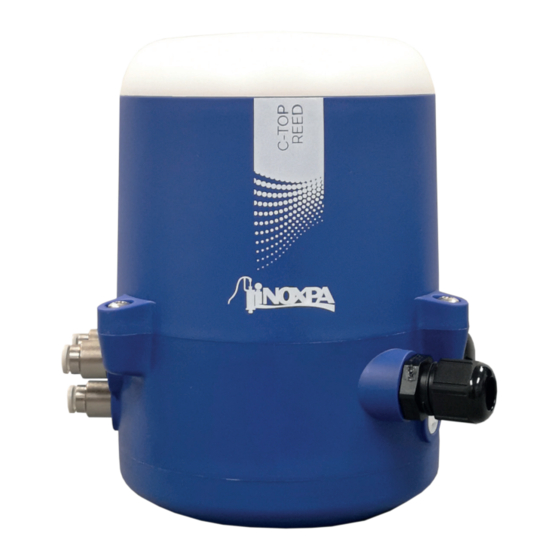
General Information 4. General Information 4.1. DESCRIPTION The C-TOP Reed is a control head that adapts to all of the INOXPA actuators to automate pneumatic drive process valves. The control head contains up to a maximum of three solenoid valves, two magnetic targets fix to the adapter shaft and an electronic module formed by three sensors connected to three visual indicators. (LEDs). Through external signals, the solenoid valves which control and act on the valve ... -
Page 9: Installation
5. Installation 5.1. RECEPTION OF THE CONTROL HEAD INOXPA is not liable for any deterioration of the material caused by its transport or unpacking. When receipt the control head, check to see whether all the parts listed on the delivery slip are... - Page 10 Installation To mount the control head on the actuator of the valve follow the next process: 1. sure that the adapter shaft of the valve is suitable for the C-TOP Reed, 2. remove the control head cover (02) by loosening the screws (01), 3. place the control head on the actuator, 4.
-
Page 11: Pneumatic Installation Of The Control Head
Cut the air hoses at the needed length before starting the pneumatic installation. To perform the pneumatic installation follow the next process: 1. connect the air hoses between air connections A1, A2 and/or A3 of the C-TOP Reed and the valve actuator’s air connections, 2. -
Page 12: Electrical Installation Of The Control Head
The control head C-TOP Reed is available with digital 24V DC communication for 0, 1, 2 or 3 solenoid valves. 5.7.1. Electrical installations with digital communication 24V DC... -
Page 13: Start-Up
The three sensors activate different outputs according to the selected configuration. The next table details the output that activates each sensor in each configuration. Conf. DIP 1 DIP 2 OUTPUT 1 OUTPUT 2 OUTPUT 3 middle upper lower lower upper upper lower upper middle Distribution of the sensors in the electronic module DIP switches Therefore, the manner of the situate the targets will depend on the selected configuration. The position of DIP 3 and DIP 4 is indifferent to any operating mode of the control head. INOXPA S.A.U. 10.427.30.01EN · (0) 2022/06... -
Page 14: Recommended Settings
2. place the valve in the desired position, 3. move the first target along the adapter shaft until si- tuate it up to the corresponding sensor (the LED of the output associated will be illuminated) and tighten the stud to fix it with Allen key number 2, 4. move the second target in the same manner as the first. INOXPA S.A.U. 10.427.30.01EN · (0) 2022/06... -
Page 15: Operating Problems
Solenoid valve break Replace the solenoid valve Check that each pneumatic hose Wrong operation of the process The pneumatic connections are is connected to the corresponding valves not correctly connected output of the control head INOXPA S.A.U. 10.427.30.01EN · (0) 2022/06... -
Page 16: Technical Specifications
0,35 W 8.5. COMMUNICATION Digital 24 V DC Operating voltage 24 V DC ± 10% Outlets PNP normally open push-in type, nominal cable section 0,2 to 1,5 mm (22 AWG to Terminal 16 AWG) cable gland M16 x 1,5 (4 to 10 mm Main input diameter cable) INOXPA S.A.U. 10.427.30.01EN · (0) 2022/06... -
Page 17: Dimensions
Technical Specifications 8.6. DIMENSIONS 8.7. EXPLODED DRAWING AND PARTS LIST Position Description cover screws cover cover seal base screws solenoid valves electronic module pneumatic ports cable gland base upper target lower target base seal INOXPA S.A.U. 10.427.30.01EN · (0) 2022/06... - Page 18 NOTES ________________________________________________________________________ ________________________________________________________________________ ________________________________________________________________________ ________________________________________________________________________ ________________________________________________________________________ ________________________________________________________________________ ________________________________________________________________________ ________________________________________________________________________ ________________________________________________________________________ ________________________________________________________________________ ________________________________________________________________________ ________________________________________________________________________ ________________________________________________________________________ ________________________________________________________________________ ________________________________________________________________________ ________________________________________________________________________ ________________________________________________________________________ ________________________________________________________________________ ________________________________________________________________________ ________________________________________________________________________ ________________________________________________________________________ ________________________________________________________________________ ________________________________________________________________________ ________________________________________________________________________ ________________________________________________________________________ ________________________________________________________________________ ________________________________________________________________________ ________________________________________________________________________ ________________________________________________________________________...
- Page 19 NOTES ________________________________________________________________________ ________________________________________________________________________ ________________________________________________________________________ ________________________________________________________________________ ________________________________________________________________________ ________________________________________________________________________ ________________________________________________________________________ ________________________________________________________________________ ________________________________________________________________________ ________________________________________________________________________ ________________________________________________________________________ ________________________________________________________________________ ________________________________________________________________________ ________________________________________________________________________ ________________________________________________________________________ ________________________________________________________________________ ________________________________________________________________________ ________________________________________________________________________ ________________________________________________________________________ ________________________________________________________________________ ________________________________________________________________________ ________________________________________________________________________ ________________________________________________________________________ ________________________________________________________________________ ________________________________________________________________________ ________________________________________________________________________ ________________________________________________________________________ ________________________________________________________________________ ________________________________________________________________________...
- Page 20 NOTES ________________________________________________________________________ ________________________________________________________________________ ________________________________________________________________________ ________________________________________________________________________ ________________________________________________________________________ ________________________________________________________________________ ________________________________________________________________________ ________________________________________________________________________ ________________________________________________________________________ ________________________________________________________________________ ________________________________________________________________________ ________________________________________________________________________ ________________________________________________________________________ ________________________________________________________________________ ________________________________________________________________________ ________________________________________________________________________ ________________________________________________________________________ ________________________________________________________________________ ________________________________________________________________________ ________________________________________________________________________ ________________________________________________________________________ ________________________________________________________________________ ________________________________________________________________________ ________________________________________________________________________ ________________________________________________________________________ ________________________________________________________________________ ________________________________________________________________________ ________________________________________________________________________ ________________________________________________________________________...
- Page 21 How to contact INOXPA S.A.U.: Contact details for all countries are continually updated on our website Please visit www.inoxpa.com to acces the information. INOXPA S.A.U. Telers, 60 - 17820 - Banyoles - España...
Need help?
Do you have a question about the C-TOP Reed and is the answer not in the manual?
Questions and answers