Table of Contents
Advertisement
Quick Links
Advertisement
Table of Contents

Related Manuals for Oasis PCPEBQ


Summary of Contents for Oasis PCPEBQ
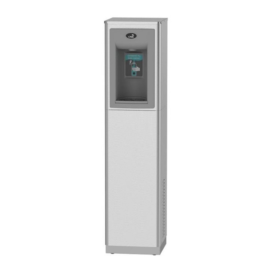
- Page 1 FREE STANDING CONTACTLESS BOTTLE FILLER WITH QUASAR UV-C LED Installation Instructions For: UNFILTERED: PCPEBQ PCPEBQY (230V) PCP10EBQ PCP10EBQY (230V) FILTERED: PF2CPEBQ PF2CP10EBQ OASIS International 222 East Campus View Blvd. Columbus, OH 43235 614-861-1350 www.oasiscoolers.com...
-
Page 2: Product Specifications
INDEX PRODUCT SPECIFICATIONS IMPORTANT REQUIREMENTS SAFETY WARNINGS QUASAR UV-C LED OPERATION GETTING STARTED PROPER QUICK CONNECT FITTING CONNECTION INSTRUCTIONS INSTALLATION SET-UP GUIDE FOR DISPENSER PCB ELECTRONICS 1. PRODUCT SPECIFICATIONS Dimensions: Depth 13-11/16” [348 mm] Width 12-1/8” [307.8mm] Height 49-11/16” [1262 mm] R-134a Refrigerant: 115 VAC, 60 HZ or 220/240 VAC, 50/60HZ –See Data Plate... - Page 3 ROUGHING-IN AND DIMENSIONAL DRAWING...
-
Page 4: Important Requirements
2. IMPORTANT REQUIREMENTS • Use only original and new parts to guarantee the reliability, optimization, and performance of the OASIS water machine. • Always wear proper protection when performing any type of service or maintenance. • When cleaning the unit, do not use corrosive acidic products, or metal brushes. -
Page 5: Operation
4. QUASAR UV-C LED OPERATION QUASAR is a form of dispense point water treatment that utilizes UV-C LED’s to inactivate pathogens. Operation: The QUASAR activation is automatic. The UV-C LED’s turn ON when water is dispensed and OFF when the dispense stops. During non-use periods the QUASAR automatically cycles ON for ten seconds every ten minutes. -
Page 6: Led Indicator
4. QUASAR UV-C LED OPERATION Display LED Indicator Condition Display Action LED Color Ensure water supply is ON. While dispensing, UVC If initial start-up: Activate the “UVC OFF- TURN Orange temperature is too high. bottle filler to dispense water. ON WATER SUPPLY” LED will turn BLUE when water flows. -
Page 7: Getting Started
5. GETTING STARTED: What’s Included: CONTACTLESS BOTTLE FILLER STABILIZER BRACKET DRAINPIPES, DRAIN ELBOWS and P-TRAP (NOT SHOWN) VERSAFILTER III (FILTERED MODELS ONLY) REMEDI FILTER (FILTERED MODELS ONLY) STABILIZER BRACKET Remedi filter element VERSAFILTER III (filtered models only) (filtered models NOTE: This comes only) installed in the cooler CONTACTLESS... -
Page 8: Proper Quick Connect Fitting Connection Instructions
6. PROPER QUICK CONNECT FITTING CONNECTION INSTRUCTIONS: Quick-Connect Fittings • If you need to cut the plastic tubing, be sure to cut tube ends square and straight. Do not deform the tube (i.e., cause tube to compress its diameter so it is no longer round, or it may result in a water leak at the fitting). -
Page 9: Installation
7. INSTALLATION: STEP 1 & 2: Carefully unpack Water Dispenser. Remove Front Panel by removing the 2 screws at the bottom of the panel on the sides. Carefully remove Drainpipes, Drain Elbows and P-Trap packaged inside unit. See Diagram 1 and 2. DIAGRAM 1 DIAGRAM 2 REMOVE... - Page 10 7. INSTALLATION: STEP 3 & 4: Assemble Drainpipes, Drain Elbow and P-Trap to Driptray Tailpiece. Locate the Snap Bushing in the back of the cabinet and feed 1-1/2” OD P-Trap through the hole. See Diagram 3 and 4. DRAINPIPE QTY. 2 DRIPTRAY TAILPIECE DRIPTRAY...
- Page 11 7. INSTALLATION: STEPS 5 through 7 (filter model only) Note: If this unit is equipped with a two stage filtration system, then the remedi filter was shipped installed. The VersaFilter III was placed in the cooler for shipping. Unpack the VersaFilter III and remove the sanitary cap. Looking at the filter top, orient the filter so that the rectangular lug, on top of the filter faces forward.
- Page 12 7. INSTALLATION: STEPS 8 through 10: Connect 1/4” OD water supply tube to 1/4” quick connect fitting on the back of the unit. Refer to Section 5 for instructions on how to properly connect to quick connect fittings. IMPORTANT: Before connecting water supply to dispenser, flush building water supply.
- Page 13 7. INSTALLATION: STEPS 11 through 18: 11. Rotate the fan blade to see that it is free of obstructions. 12. ENERGIZING UNIT: Check the available power supply against the water dispenser data plate to ensure correct electrical service. This water dispenser is intended to be connected to a 20A minimum ground fault circuit interrupting (GFCI) device to meet UL requirements (115V product).
- Page 14 10 seconds. ( If the Quasar fails, the water will not dispense when “N” is selected. If “Y” is selected, water can still dispense if Quasar fails. ) P/N 030099-709, 3/2023 ©2023 LVD Acquisition, LLC; OASIS is a registered trademark of LVD Acquisition, LLC dba OASIS International.
Need help?
Do you have a question about the PCPEBQ and is the answer not in the manual?
Questions and answers