Oasis PGN8EBF Installation Instructions Manual
Wall mounted contactless refrigerated bottle filler
Hide thumbs
Also See for PGN8EBF:
- Installation instructions manual (25 pages) ,
- Installation instructions manual (21 pages) ,
- Installation instructions manual (23 pages)

Related Manuals for Oasis PGN8EBF


Summary of Contents for Oasis PGN8EBF
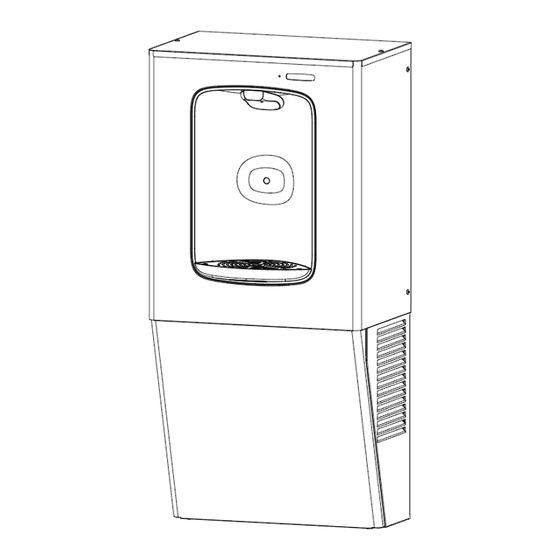
- Page 1 PGN8EBF PGN8FEBF (filtered) PGN8EBF, PGN8FEBF Shown QUASAR UV-C LED WATER TREATMENT PGN8F2EBQ (filtered) Wall Mounted Contactless Refrigerated Bottle Filler INSTALLATION INSTRUCTIONS...
-
Page 2: Section 1: Getting Started
Section 1: Getting Started What’s Included: Drainpipe Drain Elbow Filter Filter (Included in (Included in Filtered Models Only) Filtered Model: T15 Torx Screws PGN8F2EBQ Only) Tools & Hardware Required: • Means to cut 1-1/4” drainpipe • Electric drill/driver • T15 Torx screwdriver and bit •... - Page 3 Section 2: IMPORTANT QUASAR REQUIREMENT CAUTION: DO NOT ACTIVATE BOTTLE FILLER ELECTRIC EYE SENSOR WITHOUT RUNNING WATER THROUGH THE UV-C MODULE. OPERATING THE UV-C MODULE DRY MAY DAMAGE THE UV-C LED’S. Section 3A: QUASAR UV-C LED OPERATION ® QUASAR is a form of dispense point water treatment that utilizes UV-C LED’s to inactivate pathogens.
- Page 4 Section 3B: QUASAR LED Indicator Key Display LED Indicator Display Condition Action LED Color Ensure water supply is ON. While dispensing, UVC “UVC OFF- TURN If initial start-up: Activate the Orange temperature is too high. bottle filler to dispense water. ON WATER SUPPLY”...
- Page 5 Section 4: Single Level Rough-In Drawing PGN8EBF PGN8FEBF PGN8F2EBQ NOTES: 1. TRAP, STOP VALVE AND ELECTRICAL OUTLET NOT FURNISHED. 2. ALLOW 4 INCHES [102MM] MIN. PER SIDE FOR VENTILATION. 3. RECOMMENDED ADULT BARRIER FREE HEIGHT INSTALLATION SHOWN. REDUCE HEIGHT BY 3 INCHES FOR INSTALLATIONS USED PRIMARILY BY CHILDREN AGES 12 AND YOUNGER.
-
Page 6: Section 5: Preparation
Section 5: Preparation Read these instructions before installing the unit. 1. Inspect the carton and water cooler for evidence of rough handling and concealed damage. Damage claims should be filed with the carrier. 2. Locate and install plumbing and electrical service, if required, in accordance with Roughing-in Drawing. -
Page 7: Chiller Installation
CHILLER INSTALLATION... - Page 8 Section 6: Chiller Installation 1. Install the wall hanger onto the wall according to the rough-in drawing. See page 3. The Wall hanger is shipped fastened to the back of the chiller unit. Install wall hanger bracket with three chosen anchors (not provided) Refer to rough in drawing for install locations and...
-
Page 9: Bottle Filler Installation
BOTTLE FILLER INSTALLATION... -
Page 10: Section 7: Installation
Section 7: Installation 1. Unit comes partially assembled for shipping. Remove the kit from the packaging and separate it into the assemblies and components shown below. Tool Needed: T15 Torx bit Frame Filter Support Drip Tray Assembly Cabinet Assembly PGN8EBF Shown. - Page 11 Section 7: Installation 2. Place the bottle filler frame against the wall and set it onto the top flange of the chiller frame. Align the side edges of the bottle filler and cooler frames to center the frame. 3. Affix the frame to the wall with at least 4 anchors into any appropriate anchor points through the staggered slotted holes.
- Page 12 Section 7: Installation 4. With 4x T15 Torx screws, assemble the drip tray assembly to the center bracket and wall frame. Put IN FRONT OF center bracket 5. Attach the filter support bracket with 2x T15 Torx screws to the frame and drip tray support bracket.
- Page 13 Section 7: Installation 6. Attach one of the drain elbows to the drip tray stem. Insert the drainpipe provided into the elbow and then attach another elbow onto the pipe. Use the remaining drainpipe and connect the drip tray drainage system to the installed P-trap. NOTE: Drainpipes will need to be positioned and cut to length as needed.
- Page 14 Section 7: Installation 8. If the outer edge of the drip tray is not properly aligned, loosen the screws mounting the filter support and drip tray bracket to the frame and push forward or back as needed. Then retighten the screws. Slotted Holes...
- Page 15 Section 7: Installation FOR UNFILTERED MODEL ONLY. Route the insulated cold water-out line up into the bottle filler cabinet and connect it to the solenoid valve located in the alcove. Solenoid Valve ¼” Water Line With Insulation Tubing (Provided)
- Page 16 Section 7: Installation FOR FILTERED MODEL PGN8FEBF ONLY. Water Line Diagram FILTER SOLENOID DISPENSE VALVE NOZZLE INLINE STRAINER,TUBE, AND REDUCER FTG. PROVIDED. BUILDING INLET WATER CHILLER IMPORTANT: Flush filter before connecting water line to Chiller cooling tank inlet.
- Page 17 Section 7: Installation FOR FILTERED MODEL PGN8F2EBQ ONLY. Water Line Diagram FILTER FILTER SOLENOID UV-C LED VALVE INLINE STRAINER,TUBE, AND REDUCER FTG. PROVIDED. BUILDING INLET WATER CHILLER IMPORTANT: On Quasar model Flush filters before connecting water line to Chiller cooling tank inlet. IMPORTANT: When replacing filter cartridge, turn off water supply.
- Page 18 Section 7: Installation FOR FILTERED MODEL PGN8FEBF ONLY. Insert filter cartridge, rotate ¼ turn until locked. Connect the preassembled water source line to the shutoff valve. Note that there is an in-line strainer inside the copper tubing of the water source line. IMPORTANT: It is required to keep in-line strainer in system for unit to function properly;...
- Page 19 Section 7: Installation FOR FILTERED MODEL PGN8F2EBQ ONLY. 9. Insert filter cartridge, rotate ¼ turn until locked. Connect the preassembled water source line to the shutoff valve. Note that there is an in-line strainer inside the copper tubing of the water source line. IMPORTANT: It is required to keep in-line strainer in system for unit to function properly;...
- Page 20 Section 7: Installation FOR FILTERED MODEL ONLY. After the frame has been installed (not shown), insert the insulated water line from the cold tank into the solenoid located at the top of the alcove assembly. Cooling Tank Water Outlet Solenoid Valve Inlet Cooling Tank Water Outlet Line From...
- Page 21 Activate Bottle Filler sensor and dispense water into a container until the water becomes clear. 12. Refer to the “SET-UP GUIDE FOR OASIS HANDS-FREE BOTTLE FILLER ELECTRONICS” program guide for further programming.
- Page 22 14. Turn ON water supply and check for leaks. 15. Plug bottle filler cord into the electrical outlet. The bottle filler will auto-calibrate and be set up specifically for that installation. Refer to the “SET-UP GUIDE FOR OASIS HANDS-FREE QUASAR BOTTLE FILLER ELECTRONICS” program guide for further programming.
- Page 23 Section 7: Installation Once the unit has been verified to be functioning properly, install the front cover panel by inserting the top flanch up between the wrapper and center bracket, then tipping the panel back to the fountain. Secure it with the 2x #8 hex or 2x T15 screws at the base of the unit. INSTALLATION COMPLETE.
- Page 24 Section 8: Maintenance and Decommissioning Maintenance 1. Inspection of condenser should be made at 3-month intervals. To remove dirt and lint from condenser, disconnect power supply cord, then use small stiff non-wire or vacuum cleaner attachment brush. Observance of this procedure will ensure adequate air circulation through condenser so operation is efficient and economical.
- Page 25 WARNING The warranty and the Underwriters' Laboratory Listing for this machine are automatically voided if this machine is altered, modified, or combined with any other machine or device. Alteration or modification of this machine may cause serious flooding and/or hazardous electrical shock or fire. EXCEPT AS SET FORTH HEREIN, THE MANUFACTURER MAKES NO OTHER WARRANTY, GUARANTEE OR AGREEMENT EXPRESSED, IMPLIED OR STATUTORY, INCLUDING ANY IMPLIED WARRANTY OR MERCHANTABILITY OR...
-
Page 26: Installation Instructions
Installation Instructions PGN8EBF, PGN8FEBF Shown P/N 030099-704 Rev. B, Date: 02/2024 OASIS INTERNATIONAL 222 East Campus View Blvd. © 2024 LVD Acquisition, LLC Columbus, OH 43235 Oasis is a registered trademark of LVD Acquisition, LLC dba 614-861-1350 Oasis International www.oasiscoolers.com...
Need help?
Do you have a question about the PGN8EBF and is the answer not in the manual?
Questions and answers