Oasis Quasar PWEBQ Installation Instructions Manual

Oasis Quasar PWEBQ Installation Instructions Manual

Hands-free bottle filler

Advertisement

QUASAR Hands-Free Bottle Filler
UVC-LED WATER TREATMENT
Model PWEBQ and PWF2EBQ (retro fit)
and P*EBQ Family of Drinking
Fountains/Bottle Filler combo
Installation Instructions
The Hands-Free Bottle Filler mounts directly above Versacooler
products. If the cooler electrical outlet does not have two useable plugs, an
outlet splitter will need to be used.
If installed onto a refrigerated cooler, chilled water can be dispensed through
the Bottle Filler. Otherwise, room temperature water will be dispensed.
The Bottle Filler is shipped partially assembled.
On the combo units, the cooler is plumbed and ready to attach to the Bottle
Filler.
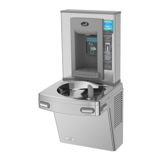
When completed, the finished assembly will look like this:
Water Coolers
OR
I and II
®
1

Advertisement

Table of Contents
loading

Summary of Contents for Oasis Quasar PWEBQ

  • Page 1: Installation Instructions

    Water Coolers QUASAR Hands-Free Bottle Filler UVC-LED WATER TREATMENT Model PWEBQ and PWF2EBQ (retro fit) and P*EBQ Family of Drinking Fountains/Bottle Filler combo Installation Instructions The Hands-Free Bottle Filler mounts directly above Versacooler I and II ® products. If the cooler electrical outlet does not have two useable plugs, an outlet splitter will need to be used.
  • Page 2 Section 1: Getting Started What’s Included: Top Cap Quasar Hands-Free Bottle Filler Snap bushings 7/8” and 1½” 38” of ¼ OD plastic tubing with 19” of sponge tubing insulation (included with “Quasar Bottle Filler ready” coolers) Quick connect tee fitting Installation instructions remedi...
  • Page 3 Section 2: Rough In Drawing Oasis PWEBQ: Versacooler® II Models PAC, P8AC with Hands-Free Bottle Filler...
  • Page 4 Section 2: Rough In Drawing Oasis PWEBQ: Versacooler® II Split Level Models with Hands-Free Bottle Filler * On split level models, the Bottle Filler must be mounted on the low unit in order to meet ADA guidelines.
  • Page 5 Section 3A: Installation Note: Proceed to Section 3B Step 5 “Final steps for both product families” if the cooler is purchased “Quasar Bottle Filler or VersaFiller ready”. A: Drilling hole in the top for water line connection. Disconnect power by UNPLUGGING unit. It might be necessary to remove the front panel to get access to the power.
  • Page 6 USE THIS TEMPLATE TO MARK THE HOLE LOCATION ON COOLER TOP...
  • Page 7 Section 3B: Installation VersaCooler to Quasar Bottle Filler Plumbing Diagram OPTIONAL VERSAFILTER II OPTIONAL BOTTLE FILLER FILTER SOLENOID UV LED VALVE INLINE STRAINER,TUBE, AND REDUCER FTG. PROVIDED WITH FOUNTAIN. BUILDING INLET WATER VERSACOOLER...
  • Page 8 Section 3B: Installation Two VersaCoolers to Quasar Bottle Filler Plumbing Diagram BOTTLE FILLER SOLENOID UV LED VALVE OPTIONAL VERSAFILTER II OPTIONAL FILTER VERSACOOLER VERSACOOLER T-FITTING INLINE STRAINER,TUBE, AND REDUCER FTG. PROVIDED WITH FOUNTAIN. BUILDING INLET WATER...
  • Page 9 Section 3B: Installation B: Connecting the water line Note: If you are retrofitting the Bottle Filler to an existing cooler, follow the instructions starting on page 11. For the single “Bottle Filler ready” cooler, the tube to connect to the Bottle Filler is found inside the access panel (the compressor compartment).
  • Page 10 The tee and tube to the Bottle Filler are packaged with the PWEBQ unit. One branch of the tee will supply the valve on the dummy unit, the other branch of the tee will connect to the Bottle Filler. If a filter is being installed, cut a piece of tubing about 3” long to insert optional flow switch right after filter and before tee.
  • Page 11 To retrofit the Versafiller to an existing unit, follow the instructions below: If the cooling tank is non-pressurized, then go to the “Pressurizing the cooling tank” addendum section. Otherwise, proceed to step 1 below. Non-pressurized units are single units made since December of 2009. Refer to the schematic below to identify the system that you have.
  • Page 12 Section 3B: Installation: For the P8AC Version: Versacooler II Disconnect tubing from the elbow on the valve. Using the 38” piece of tubing provided, cut 6” and install it 32” tubing on the end of the TEE. Install the remaining tubing onto the branch of the TEE.
  • Page 13 Section 3B: Installation: For the P8AM Version: Versacooler I Remove tar tape Remove tar tape from the insulation on the outlet tube. Pull back insulation and cut the copper tube with a tubing cutter. Cut where there is at least 1 inch of straight tubing on each side of the cut.
  • Page 14 Section 3B: Installation: Final steps for both product families: Feed tube up through the top and attach the top to the cooler. To solenoid valve inlet. TIP: For the P8AM, it is easier to connect the outlet tube to the bubbler if the front nose is removed.
  • Page 15 Section 3C: Installation C: Mounting the frame to the wall Place rubber gasket on top of the cooler so it is centered left/right and against the wall. Set the wall frame onto the gasket. Center it left/right and push it against the wall and mark hole locations for wall fasteners.
  • Page 16 Section 3C: Installation Slide sponge tubing insulation over water line. Connect the tubing to the INLET of the solenoid on the back of the Hands-free Bottle Filler assembly. Connect tube to inlet of the valve Plastic tubing Sponge tubing insulation...
  • Page 17 Section 3D: Installation D: Attaching the Tether Install bottle filler tether with the steps below. Attach the tether line assembled to the bottle filler dispense bracket to the cleat on the mounting frame. Push loop through hole. Put loop around one side of the cleat.
  • Page 18 Section 3: Installation The tether keeps the bottle filler secured to the frame when changing the filter, if installed. Make sure the tether is installed properly to avoid accidental damage to the unit. Before the Bottle Filler cabinet is set into place, feed the terminals on the power supply power cord and the long green ground wire through the bushing on the cooler top.
  • Page 19 Section 3: Installation MAKE SURE the cabinet fits into the groove in the rubber gasket on both sides and front of the wrapper. Bottle Filler cabinet Groove in the gasket See next page to secure Bottle Filler assembly to frame with torx screws.
  • Page 20 Section 3D: Installation Torx screw Insert bottle Torx screw 10. Attach Bottle Filler assembly to the frame using two (2) torx screws. Remove the Top Cap and two (2) torx screws used for mounting. 11. Plug bottle filler cord into the electrical outlet. The bottle filler will auto-calibrate and be set up specifically for that installation.
  • Page 21 Section 4: Set-up guide for bottle filler electronics Factory default program settings are: • Units - Gallons • Bottle Count = 0.5L (1 Bottle) • Unfiltered unit • Flow Rate = 1.2 GPM • Flow Meter = Rate Selected • 20 second maximum dispense time •...
  • Page 22 Addendum Section: Pressurizing Cooling Tank The water should already be turned OFF and the power disconnected. Unit as it appears with top removed STEP 1 Unplug un-insulated water line from water valve inlet (quick-connect elbow located left side of water valve facing the front of the cooler).
  • Page 23 STEP 3 Plug un-insulated tubing that was removed in step 1 into quick-connect elbow leading to the cooling tank from step 2. STEP 4 Unplug tubing that is connected to the water valve outlet (quick- connect elbow located on the right side of valve facing the cooler).
  • Page 24 Step 6 Unplug quick-connect tubing from the cooling tank outlet. Do not set it down. Step 7 Using tubing removed in step 6, plug into quick-connect elbow on the right side of the valve. (be sure to route the tubing under existing tubing installed in step 4 as shown)
  • Page 25 Section 5: Parts Breakdown...
  • Page 26 Section 5: Parts Breakdown...
  • Page 27 P/N 030099-601 Date: 10/2019 © 2019 LVD Acquisition, LLC OASIS INTERNATIONAL 222 East Campus View Blvd. Oasis and Versacooler are registered trademarks of LVD Acquisition, LLC dba Oasis International. Columbus, OH 43235 614-861-1350 Haws is a registered trademark of HAWS Corporation.

Table of Contents