Redx RX Series User Manual
Hide thumbs
Also See for RX Series:
- User manual (49 pages) ,
- User manual (32 pages) ,
- User manual (40 pages)
Table of Contents
Advertisement
Quick Links
Advertisement
Table of Contents

Related Manuals for Redx RX Series


Summary of Contents for Redx RX Series
- Page 1 User Manual RX SERIES INVERTER RX-5000AC...
- Page 2 R e d...
- Page 3 Software Licenses It is prohibited to use data confirmed in firmware or software developed by Redx, in part or in full, for commercial purposes by any means. It is prohibited to perform reverse engineering, cracking, or any other operations that compromise the original program design of the software developed by Redx.
- Page 4 About This Manual This manual mainly describes the product information, installation, operation, and maintenance guidelines of the Redx inverter (RX-5000AC). Please read this manual carefully before using this product and store the manual in a safe place. Redx will not notify the user of any changes to this manual.
-
Page 5: Table Of Contents
6.3 Operation Modes……….………………………………...……………......30 6.4 Communication……….………………………………...……………........32 7 RX-5000AC System Turn On and Turn Off……….……………………..…......32 7.1 Turn on/off RX-5000AC….…..…………………………...…...........32 8 Troubleshooting & Maintenance……….………………………………........32 8.1 Troubleshooting……….………………………………...…………........32 8.2 Maintenance……….………………………………...……………........35 8.3 Routine Maintenance……….………………………………...………......36 9 Redx Power App……….………………………………...……………........37 10 Quality Assurance……….………………………………...……………........37 11 Appendix……….………………………………...……………..........38 11.1 Optional Accessories……….………………………………...………......38 12 Contact……….………………………………...…………….............39... -
Page 6: Safety
(a) Do not open the case as risk of electric shock (b) Maintenance should be carried out by a professional licensed technician (c) Read this manual before operating the system. Redx is not responsible for failure or loss arising out of improper operation. - Page 7 Table 1-1 - Warnings Danger! Removal of any protection, incorrect use, incorrect installation, or incorrect operation may result in death/serious personal injury or device damage. Transportation, loading and unloading, installation, start-up and maintenance must be carried out by qualified or trained engineer/technician. Danger! Before maintenance or touching any parts, or installation, make sure that the energy storage unit is disconnected and wait 5 minutes to ensure that the...
- Page 8 Warning! The product is not tested to section 5 of AS/NZS 4777.2:2020 and is not to be used in multiple inverter combinations without additional considerations by the system designer Warning! The load capacity of the output of the inverter load is as follows: Inductive load (such as air conditioning, washing machine, motor, etc.).
-
Page 9: Product Introduction
2 Product Introduction 2.1 System Diagram RX-5000AC is an AC-coupled inverter. AC-coupled inverter provides advanced storage and upgrading solutions to the PV grid-connected inverters(any brand or model), enabling the existing system to benefit from energy storage capability and emergency power supply. The AC-coupled inverter will detect the energy generated by the grid-connected inverter, which will be used by the local load first, and the rest will be stored in the battery through the AC-coupled inverter, and the surplus energy will be fed back to the grid. - Page 10 Figure 2.1.2 shows the typical application of the RX-5000AC inverter. Blue indicates a power cable, indicates a signal cable The explanation is as follows: Table 2.1.2 - Diagram elements explained Number Name PV Panel Circuit Breaker RX-5000AC Inverter Regular Loads Smartmeter/CT Grid Low Voltage Battery...
- Page 11 Blue hidden indicates a signal cable, indicates wireless communication The explanation is as follows: Table 2.1.3 - Diagram elements explained Number Name RX-5000AC Redx Power App 4G Module Internet Wi-Fi Router Cloud Server Wi-Fi Module Rev 20230602 RX - 5000AC...
-
Page 12: Product Details
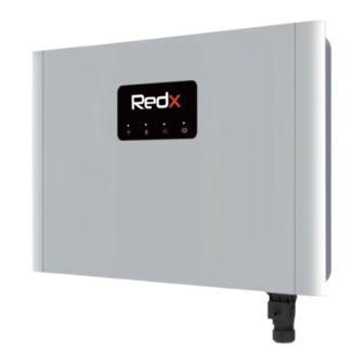
2.2 Product Details 2.2.1 Appearance and Dimensions 6 7 8 Figure 2.2.1 RX-5000AC terminals Table 2.2.1 - Diagram elements explained Items Name On/off Switch LED interface WIFI / 4G Communication connector Grid connector Protective grounding / Earth link EPS LOAD connector N.C. - Page 13 SOC Indicator Inverter Bracket Inverter Bracket 2 Battery Bracket Note: The inverter is only compatible with Redx Batteries. 2-8 (10-40kWh) Redx RX-0050 (lithium iron phosphate) batteries must be installed to the inverter. Rev 20230602 RX - 5000AC Page 8 of 40...
- Page 14 2.2.2 Dimensions 175mm 620mm 400mm RX-5000AC 175mm 620mm 1400mm Figure 2.2.3 RX-5000AC Dimensions Rev 20230602 RX - 5000AC Page 9 of 40...
-
Page 15: Led Indicator Panel And Switches
2.3 LED Indicator Panel and Switches Main power switch ON - OFF Figure 2.3.1- RX-5000AC On-Off switch Table 2.3.1 - Status LED elements explained LED indicator Startup conditions are not met Green flash Green Normal System indicator Yellow System warning System fault None No PV... - Page 16 Communication Interface Pin Definition Figure 2.3.2 - RX-5000AC Communication interface Table 2.3.2 - Diagram elements explained group Group Definition DRM0- Dry contact 1 Public Dry contact 1 open DRM0+ Dry contact 1 close Dry contact 2 Public 485C- Dry contact 2 open 485C+ Switch input Dry contact 2 close...
-
Page 17: Technical Data
2.4 Technical Data GENERAL Internal on/off grid switch Operating temperature range -20℃ to +50℃ Display/indicators LED indicators Cooling Convection Size W*H*T 620mm X 400mm X 162mm Weight 22.5KG IP rating IP65 Protective Class Class I Altitude <2000 m Over Voltage Category AC:OVC III DC:OVC II Others: OVC I The decisive voltage class DC,AC:DVC C,other ports: DVC A... - Page 18 BAT LV Rated Power Rated voltage range 42~58Vdc Max Charge/Discharge Current 115Adc PROTECTION FUNCTIONS Islanding protection Anti-backflow DC reverse connection protection AC output short circuit protection DC fuse (battery side) Overcurrent protection Over-temperature protection COMMUNICATION RS485_A&CAN RS485_B WIFI/4G/BLUETOOTH RS485_C Meter/Turbine/EV RS485_D Parallel/Reserved External CT...
-
Page 19: Product Features
2.5 Product Features a. Backup power supply b. Compatible with various application scenarios c. Intelligent management d. Remote scheduling e. Multiple protection 3 Installation Storage Store the storage unit properly when the unit is not installed immediately Store the unit in the original packaging box Storage temperature should be always between 0°c and 50°c+ The packaging box should be upright. - Page 20 RX-5000AC Standard Accessories WI-FI/4G Dongle RX-5000AC Inverter Bracket Hole template Expansion Bolt (Optional) 1PCS 1PCS 1PCS 1PCS 10PCS Bootlace Communication Bootlace EPS Load Connector Ferrule-6012 Connector Ferrule-0510 Grid Connector 1PCS 3PCS 1PCS 30PCS 1PCS Smartmeter+CT SC6-6 CT-Cable (Optional) Document 2PCS 2PCS 2PCS 4PCS...
- Page 21 RX-5000AC Base components Base leveling screw Base M6*14_Countersunk Screw 1PCS 4PCS 2PCS Figure 3.0.3 - RX-5000AC base components RX-0050 Accessories Battery Body Battery Bracket Battery Cover 1PCS 1PCS 2PCS M6*50 M6*10 Expansion Bolt Countersunk Screw M6*10 8PCS 1PCS 2PCS M4*8 M4*20 Countersunk Screw Document...
-
Page 22: Installation
3.1 Installation Preparation a. Not to be installed in direct sunlight. Product is designed for indoors. Vertical mounting only. b. Install in a ventilated location. There must be enough clearance to ensure that the module operates in the optimal heat dissipation state. c. -
Page 23: Installation Tools
3.2 Installation Tools Prepare the following tools before installation: Figure 3.2.1 - RX-5000AC Installation tools Type Tool Packaging tape Marker Measuring tape Level General tools Multimeter Measurement range: Protective ≥ Utility knife Wrist strap 1100Vdc clothing Protective gloves Dust mask Ear protection Eye protection Insulated shoes... -
Page 24: Installation Guide
4 Installation Guide 4.1 Mounting guide Avoid water and electricity when drilling, bit size φ8mm, drilling depth 40mm. Expansion Bolts Hole Template Plug Spacer Plug Inverter 2.8 N.M Bracket Battery Bracket Screw Refer to the electrical connection section for wiring PROJ. -
Page 25: Electrical Connection
5 Electrical Connection An independent circuit breaker must be configured for each power interface. The table below is a recommendation for cable selection and the Recommended specifications of circuit breaker. Engineers should refer to local standards to select cables. Cable length is generally 2 to 10 meters, long cable will lead to voltage deviation from the rated value, consequently requiring an increase of the cross-sectional area. -
Page 26: Port Instruction
5.2 Port Instruction Items Name WIFI / 4G Communication Connector Grid Connector Protective Grounding LOAD Connector N.C. 4 5 6 Figure 5.2.1 - RX-5000AC Port Instruction 5.3 Earth Connection A secondary protection grounding terminal is added for the system. Ensure that the grounding resistance is less than 10 Ω... -
Page 27: Battery Power Cable Wiring
5.4 Battery Power Cable Wiring Note: you will hear a ‘Click’ sound if the battery connector is connected correctly. When removing a battery cable, press the button on the cable terminal. Click 5.5 WiFi/4G Dongle Rev 20230602 RX - 5000AC Page 22 of 40... -
Page 28: Communication Connection
Communication Connection Group Group Definition Dry contact 1 Public DRM0- Dry contact 1 open DRM0+ Dry contact 1 close Dry contact 2 public 485C- Dry contact 2 open 485C+ Dry contact 2 close Negative Input For Switch Positive Input For Switch 485D+ 485D- Reserved... - Page 29 5.6.1 Connect Battery 2 to Pin11 and Pin12 in the COM terminal of the inverter using the"Communication cable 2pin" Table 5.6.1 - RX-5000AC Communication connector Group Definition BMS_CAML BMS_CANH 5.6.2 CT/METER Connection The CT/METER is used to monitor the status of the energy consumption. Group Figure 5.6.2 - RX-5000AC Communication connector CT pins CT cable specifications: if the cable is not long enough, adding an extension cable...
-
Page 30: Grid Connection
As shown in figure 5-6.2.1 an arrow indicates the direction of the CT, pass cable through the hole of the CT then lock the CT. The RS-485 communication connection is shown as follows: Group 485C- 485C+ Figure 5.6.2.2 - RX-5000AC Communication connector 485 pins 5.6.3 Connection of DRM0 Terminal (Australia Only) When RX-5000AC is installed in some states in Australia, the DRMS terminal needs to be connected. - Page 31 Figure 5.7.1 - RX-5000AC 240V electrical connection with EPS Note: The battery inverter does not have an internal RCD as it is isolated. If an external RCD breaker is mandatory in the country of installation, it must be a type A RCD with the rating r esidual current not more than 30mA.
-
Page 32: Eps Load Connection
Steps Figure 5.7.2 - RX-5000AC Grid connector Figure 5.7.3 - RX-5000AC Grid connector assembly Note: for details about the electrical connection, see Figure 2-1.b,c,d。 1.The GRID terminal and off-grid(EPS LOAD terminal cannot be connected together, otherwise the system will be damaged. 2.The battery needs to be activated by the grid when the system starts for the first time. -
Page 33: Operation
Figure 5.8.1 - RX-5000AC EPS connector assembly Do not connect the port to other power supplies. Otherwise, the inverter may be damaged, causing risks. 6 Operation 6.1 Checklist Before Operation 1. Check whether the system is firmly installed, and the installation position is easy for operation and maintenance. - Page 34 Response Mode settings on the Deploy page which are also password protected. The installer can request the password from Redx. Figure 6-1 - Export Soft and Hard Limit settings on Deploy page Figure 6-2- Region selector in the Redx Power App Rev 20230602 RX - 5000AC...
-
Page 35: Operation Checks
If there is voltage on the grid terminals, but unit is still not illuminating the LEDs– please contact local Redx dealer. (b) Install the Redx Power APP or open web page according to the attached instructions, and then configure the WIFI connection. - Page 36 B.Off - Grid / EPS Functionality When the power grid is cut off, the system will automatically switch to off-grid mode. The system will supply power to the EPS loads through the battery. Note: under off-grid mode, the system power output rate only using the battery is 5kW.
-
Page 37: Communication
6.4 Communication The Redx unit has an external data collector, users can choose either WIFI or 4G dataloggers according to their requirements, and use their computer or mobile phone APP (Redx Power) to monitor the inverter and battery status. The default datalogger in the device uses Wi-Fi to connect to the customer's Wi-Fi router to establish an Internet connection. - Page 38 Suggestion Fault information Fault reason If the battery is connected 1. Check whether the battery cable is securely connected and whether the battery voltage The battery connection No battery is detected is normal. error 2. If the error message remains, contact installation partner.
- Page 39 1. Check whether the AC circuit breaker of the grid is disconnected and whether the connecting cables are securely connected. Islanding protection Islanding protection check 2. Check whether the grid has power. 3. If all conditions are correct and the fault still occurs, contact installation partner.
-
Page 40: Maintenance
1. Remove some loads. Ensure that the load is smaller than the maximum output power of the Output overload Overloaded outputs inverter. 2. Restart the inverter. 1. The inverter installation 1. Check whether the operating environment location is not ventilated. Radiator over exceeds the operating temperature range of the 2. -
Page 41: Routine Maintenance
The repair of the battery should be carried out or supervised by personnel with battery knowledge and necessary precautions. Do not mix batteries of different types and capacities, please use all batteries of the same model. If the inverter is not used for more than 7 days, turn off the AC input and battery input switches. -
Page 42: Redx Power App
Evidence During the warranty period, the customer shall provide the product purchase invoice and date. Since the date of purchase by the user from Redx (hereinafter referred to as the manufacturer), the user will enjoy the following after-sales warranty service 1.A 10-year warranty commences from the date of shipment from, during the warranty period... -
Page 43: Appendix
(c) The user intentionally conceals the improper use of the product during installation, wiring, operation, maintenance or other processes to the after-sales service provider of the manufacturer. *Redx reserve the right to change the contents of this specification and product performance without informing users. 11 Appendix 11.1 Optional Accessories... -
Page 44: Contact
12 Contact If you have any questions about our products, please contact our service hotline or dealers. please provide the following information when inquiring: 1.System serial number 2.System model 3.Fault code/Name 4.Briefly describe the fault symptom This image should be after Contact paragraph Rev 20230602 RX - 5000AC Page 39 of 40... - Page 45 For more information, please scan QR code or visit www.redx.com.au Download the Redx App with the above QR Code Rev 20230602 RX - 5000AC Page 40 of 40...
- Page 49 Address: Unit 2/21 Millennium Circuit, Helensvale, QLD Australia 4212 Website: www.redx.com.au Email: info@redx.com.au Phone: 61 7 5672 9983 Specifications are subject to change without advance notice.
Need help?
Do you have a question about the RX Series and is the answer not in the manual?
Questions and answers