Redx RX Series User Manual
Hide thumbs
Also See for RX Series:
- User manual (49 pages) ,
- User manual (40 pages) ,
- User manual (49 pages)
Table of Contents
Advertisement
Quick Links
Advertisement
Table of Contents

Related Manuals for Redx RX Series


Summary of Contents for Redx RX Series
- Page 1 User Manual RX SERIES ALL IN ONE 2505 PU Rev 20220610 RX2505PU Page 1 of 32...
- Page 2 Rev 20220610 RX2505PU Page 2 of 32...
- Page 3 Software Licenses It is prohibited to use data confirmed in firmware or software developed by Redx, in part or in full, for commercial purposes by any means. It is prohibited to perform reverse engineering, cracking, or any other operations that compromise the original program design of the software developed by Redx.
- Page 4 Redx energy storage system. Please read this manual carefully before using this product and store the manual in a safe place. Redx will not notify the user of any changes to this manual. This manual applies to the RX-2505PU all in one energy storage integrated system. The system must be installed by a qualified/licensed technician.
-
Page 5: Table Of Contents
7.2 Turn off RX-2505PU system……….……………………………….......23 8 Troubleshooting & Maintenance……….………………………………...… ......23 8.1 Troubleshooting……….………………………………...…………........23 8.2 Maintenance……….………………………………...……………........26 8.3 Routine Maintenance……….………………………………...………......26 9 Redx iCloud App……….………………………………...……………........26 10 Quality Assurance……….………………………………...…………….........27 11 Appendix……….………………………………...……………..........27 11.1 Product Specification……….………………………………...………......27 11.2 Optional accessories……….………………………………...………......29 12 Contact……….………………………………...……………...........30... -
Page 6: Safety
Maintenance should be carried out by a professional licensed technician Read this manual before operating the system. Redx is not responsible for failure or loss arising out of improper operation. All wiring, installation, commissioning, and other work should be done by a licensed technician... - Page 7 Table 1-1 - Warnings Danger! Removal of any protection, incorrect use, incorrect installation, or incorrect operation may result in death/serious personal injury or device damage. Transportation, loading and unloading, installation, start-up and maintenance must be carried out by qualified or trained engineer/technician. Danger! Before maintenance or touching any parts, or installation, make sure that the energy storage unit is disconnected and wait 60 seconds to ensure that the...
-
Page 8: Product Introduction
Table 1-2 - Warnings continued Warning! Product should not be installed in multiple phase combinations Warning! The load capacity of the output of the inverter is as follows: Inductive load (such as air conditioning, washing machine, motor, etc.) : Single maximum power 1.5kVA, total inductive load maximum power 2.5kVA (with grid power);... -
Page 9: Product Information
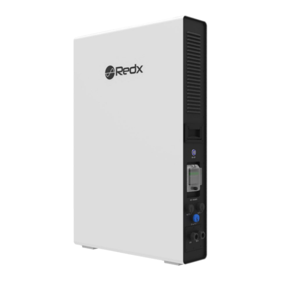
2.2 Product Information 2.2.1 Appearance and dimensions Figure 2-2 - Battery system components Table 2-1 - Battery components details Items Name Main power switch Battery air circuit-breaker DC1 input DC2 input AC-ON Indicator light DC Indicator light Grid Indicator light Charge Indicator light Battery status Nameplate... - Page 10 2.2.2 Dimension and weight Figure 2-3 - Battery system components Table 2-2 - Battery system dimensions details A(mm) B(mm) C(mm) Weight 75KG Rev 20220610 RX2505PU Page 10 of 32...
-
Page 11: Led Indicator Panel And Switches
2.3 LED Indicator Panel and Switches Table 2-3 - Battery interface details Name Items Function Switch button Turn on/off the system ON - OFF Run – Green AC-ON Fault – Red DC1 > 100W – Green (Flash) DC2 > 100W – Blue (Flash) Operating status DC1&DC2 >... -
Page 12: Name Plate Labelling
2.4 Name Plate Labelling RX-2505PU label contains the following information. Table 2-4- Battery label specifications Uninterruptible Power System RX-2505PU Model Name RX-2505PU AC Input Data 230Vac Nominal Voltage Rated Input Current Nominal Frequency 50Hz UPS Output Data Nominal AC Output Voltage 230Vac Nominal AC Output Frequency 50Hz... -
Page 13: Scope Of Delivery
2.6 Scope of Delivery Please check the condition of the packing before unpacking. If any parts are damaged or missing, contact your local supplier for help. Table 2-4 - Parts in the box RX-2505PU Power cord Mounting bracket 1PCS 1PCS 6PCS 1PCS Document... -
Page 14: Installation
3 Installation 3.1 Installation preparation a. Indoor installation only, IP32 b. Vertically mount only c. Install in a ventilated location. There must be enough clearance to ensure that the module operates in the optimal heat dissipation state. d. Install at suitable distance from any restricted areas, please review Standard ASNZS5139 e. -
Page 15: Installation Tools
3.2 Installation Tools Prepare the following tools before installation Table 3-1 - Installation tools Type Tool Packaging tape Marker Measuring tape Level General tools Multimeter Measurement range: Protective ≥ Utility knife Wrist strap 1100Vdc clothing Protective gloves Dust mask Earplugs Goggles Insulated shoes Vacuum cleaner... -
Page 16: Installation Guide
4 Installation guide 4.1 System wiring diagram Figure 4-1 shows the wiring topology (dashed boxes indicate optional components) of the RX-2505PU all-in-one uninterruptible power system Figure 4-1 - Battery system connections topology BLUE indicates wireless communication indicates an AC cable , GREEN indicates a DC cable ,... -
Page 17: Installation Procedure
4.2 Installation procedure 1. Align the hole template (locating plate) with the ground and stick it flat on the wall. 2. Align the hole template on the installation surface and drill holes with a diameter of 8mm and a depth of 40mm on the wall. 3. -
Page 18: Cable Connection
5 Cable Connection 5.1 Connect cables to the AC grid side and off-grid side RX-2505PU has terminals for on/off-grid. As shown in Figure 5-1,RX-2505PU has two AC output ports and one grid power input port. An independent AC circuit breaker must be configured for each system to safely disconnect the connected systems. -
Page 19: Ct/Meter Connection
5.2 Connect cables to DC1 and DC2 1.Connect the cable to the corresponding terminal according to the mark and tighten the screws. Figure 5-2 - DC Cable cover guide Table 5-1 - Cable and cover details Rubber Nuts DC2+ DC2- Cover grommet 2.The following table lists the parameters of DC1/DC2 cables. -
Page 20: External Rs 485 Connection
PV optimizer / wind turbine controller PV optimizer / wind turbine controller input input RX-2505PU AC OUT AC IN Load Figure 5-4 - 240V and DC connections Notice: 1. The grid terminal and off-grid terminal cannot be directly connected together, otherwise the system will be damaged. -
Page 21: Operation
If the grid power cable is OK and tightly inserted, but unit is still not illuminating the power button - please contact local Redx dealer. Install the APP or open web page according to the attached instructions, and then configure the WIFI connection. -
Page 22: Operation Modes
6.3 Operation modes 6.3.1 Normal UPS mode When the power grid is cut off, the system will automatically switch to off-grid mode. The system will supply power to the load through the battery. Note: under off-grid mode, the system power output rate is 2500W. -
Page 23: Communication
The system has an external USB interface, which contains 5V power supply and RS485 communication. Redx also has a built-in data collector. Users can choose to connect their own data collector (WIFI/GPRS function) according to their requirements, and use the computer or mobile phone APP to monitor the machine. - Page 24 Common Fault and Information below: Table 8-1 - Fault information table 1 Suggestion Fault information Fault reason If the battery is connected 1. Check whether the battery cable is securely connected and whether the battery voltage is The battery No battery is detected normal.
- Page 25 Table 8-2 - Fault information table 2 range of converter protection parameters,please automatically switches to Grid over frequency report to the power grid company. the off-grid mode. When the error disappears, the 2. If the power grid voltage or frequency is within the inverter automatically Grid underfrequency permissible range, contact the installation partner.
-
Page 26: Maintenance
9 Redx Technology App The Redx Technology APP can establish communication connection to the energy storage unit via WIFI and or 4G (optional) network. Users can use the APP to view basic information, alarms, events, set parameters, or download logs etc. -
Page 27: Quality Assurance
The user must provide proof of fault – pictures or videos with timestamps if requested by Redx. From the date of purchase by the user from Redx (hereinafter referred to as the manufacturer), the user will enjoy the following after-sales warranty service: 1. - Page 28 Table 11-1 - Product specifications table 1 Model RX - 2505PU Battery Capacity 4.8kWh 48Vdc Nominal voltage 42Vdc - 54Vdc Voltage range Battery type Max charging power / current 1500W / 30A Max discharging current DOD(%) Grid Nominal grid voltage 230Vac 180Vac-260Vac Grid voltage range...
-
Page 29: Optional Accessories
Table 11-2 - Product specifications table 2 Natural cooling Cooling Acoustic Noise 40dB Max Altitude 2000m Inverter topology No transformer DC/DC topology High frequency transformer Type of supply system on input and output TN system Communication Modbus-RTU/Modbus-TCP, CAN2.0B, TCPIP, WIFI RS485 / CAN/WIFI / GPRS Communication port 75Kg... -
Page 30: Contact
4. Briefly describe the fault symptom For more information,please scan QR code above or log in directly www.redxenergy.com.au Download the Redx App with the above QR Code Address: Unit 2/21 Millennium Circuit, Helensvale, QLD Australia 4212 Website: www.redxenergy.com.au Email: info @ redxenergy.com.au Phone: +61 7 5672 9983 Specifications are subject to changes without advance notice. - Page 31 Rev 20220610 RX2505PU Page 31 of 32...
- Page 32 尺寸:149*210mm Rev 20220610 RX2505PU Page 32 of 32 材质/克重/工艺:34P 封面封底157g铜版纸 ,内页128g铜版纸 正反印 骑马钉...
Need help?
Do you have a question about the RX Series and is the answer not in the manual?
Questions and answers