Redx RX Series User Manual
Hide thumbs
Also See for RX Series:
- User manual (49 pages) ,
- User manual (32 pages) ,
- User manual (48 pages)
Table of Contents
Advertisement
Quick Links
Advertisement
Table of Contents

Related Manuals for Redx RX Series


Summary of Contents for Redx RX Series
- Page 1 User Manual RX SERIES ALL IN ONE RX-2505PW...
- Page 3 Software Licenses It is prohibited to use data confirmed in firmware or software developed by Redx, in part or in full, for commercial purposes by any means. It is prohibited to perform reverse engineering, cracking, or any other operations that compromise the original program design of the software developed by Redx.
- Page 4 Redx energy storage system. Please read this manual carefully before using this product and store the manual in a safe place. Redx will not notify the user of any changes to this manual. This manual applies to the RX-2505PW all in one energy storage integrated system. The system must be installed by a qualified / licensed technician.
-
Page 5: Table Of Contents
7.2 Turn off RX-2505PW System……….………………………………....... 24 8 Troubleshooting & Maintenance……….………………………………...… ......24 8.1 Troubleshooting……….………………………………...…………........24 8.2 Maintenance……….………………………………...……………........27 8.3 Routine Maintenance……….………………………………...………......28 9 Redx Power App……….………………………………...……………........28 10 Quality Assurance……….………………………………...……………........28 11 Appendix……….………………………………...……………..........29 11.1 Product Specification……….………………………………...………......29 11.2 Optional Accessories……….………………………………...………......32 12 Contact……….………………………………...…………….............33... -
Page 6: Safety
⑴ Do not open the case as risk of electric shock is present. ⑵ Maintenance should be carried out by a professional licensed technician. ⑶ Read this manual before operating the system. Redx is not responsible for failure or loss arising out of improper operation. - Page 7 Danger! Removal of any protection, incorrect use, incorrect installation, or incorrect operation may result in death / serious personal injury or device damage. Transportation, loading and unloading, installation, start-up and maintenance must be carried out by qualified or trained engineer/technician. Danger! Before maintenance or touching any parts, or installation, make sure that the energy storage unit is disconnected and wait 5 minutes to ensure that the...
-
Page 8: Product Introduction
Warning! The product is not tested to section 5 of AS/NZS 4777.2:2020 and is not to be used in multiple inverter combinations without additional considerations by the system designer. Warning! The load capacity of the output of the inverter is as follows: Inductive load (such as air conditioning, washing machine, motor, etc.) : Single maximum power 1.5kVA, total inductive load maximum power 2.5kVA (with grid power). -
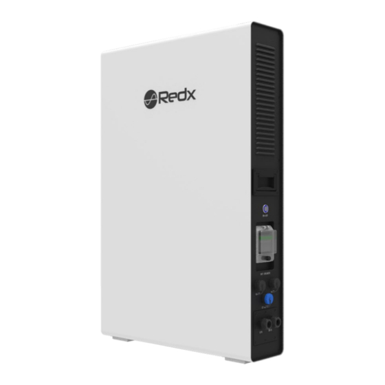
Page 9: Production Introduction
2.2 Production Introduction 2.2.1 Appearance and Dimensions Items Name Main power Switch Battery air circuit-breaker DC1 port DC2 port Battery status indicator DRM0 RJ45 Terminal RS485(USB) CT / Meter Terminal AC Terminal EPS Terminal Mounting bracke Rear cover bracket Rev 20221130 RX2505PW Page 4 of 35... -
Page 10: Dimensions And Weight
2.3 Dimension and Weight A(mm) B(mm) C(mm) Weight 75Kg Rev 20221130 RX2505PW Page 5 of 35... -
Page 11: Led Indicator Panel And Switches
2.4 LED Indicator Panel and Switches Items Name Function Switch button Turn on / off the system ON - OFF Run – Green AC-ON Fault – Red NO DC – Led off DC1>100W - Green ( Flash) DC2>100W - Blue ( Flash) Operating status DC1 &... - Page 12 Class I Ingress Protection IP32 Isolated Inverter Topology Charge: 0℃ ~ 50℃ Operation Ambient Temperature Discharge: - 20℃ ~ 50℃ Software Version V3.10.00 5min 002XOJF130001B Redx Technology Australia Pty Ltd www.redxenergy.com.au Made In China Rev 20221130 RX2505PW Page 7 of 35...
-
Page 13: Product Benefits
2.5.1 Product Benefits a. Backup power supply, peak shaving, asset management b. Integrated design, save installation time and costs c. Smart management, different operating modes d. Battery safety management system e. Remote scheduling, intelligent management f. Multiple protection 2.6 Scope of Delivery Please check the condition of the packing before unpacking. -
Page 14: Installation
3 Installation 3.1 Installation Preparation a. Indoor installation only, IP32. b. Vertically mount only. c. Install in a ventilated location. There must be enough clearance to ensure that the module operates in the optimal heat dissipation state. d. Install at suitable distance from any restricted areas, please review Standard ASNZS5139. e. -
Page 15: Installation Tools
3.2 Installation Tools Prepare the following tools before installation Table 3-1 – Installation tools Type Tool Packaging tape Marker Measuring tape Level General tools Multimeter Measurement range: Protective ≥ Utility knife Wrist strap 1100Vdc clothing Protective gloves Dust mask Earplugs Goggles Insulated shoes Vacuum cleaner... -
Page 16: Installation Guide
, indicates wireless communication The explanation is as follows: Number Name RX-2505PW AC switch Switchboard Load Smartmeter / CT Grid Optional 4G Module Auxiliary WLAN-FE Module Redx Power APP Management system Rev 20221130 RX2505PW Page 11 of 35... -
Page 17: Installation Procedure
4.2 Installation Procedure 1. Align the hole template (locating plate) with the ground and place it flat on the wall. 2. Align the hole template on the installation surface and drill holes with a diameter of 8mm and a depth of 40mm on the wall. 3. -
Page 18: Cable Connection
5 Cable Connection 5.1 Connect Cables to the AC Grid Side and off - Grid Side RX-2505PW has terminals for on and off-grid. As shown in Figure 5-1, the left terminal is the off-grid terminal (EPS) and the right terminal is the on-grid terminal. An independent AC circuit breaker must be configured for each circuit to safely disconnect then system. - Page 19 RX-2505PW AC terminals GRID/EPS wiring cover Requirements 1.Install an AC circuit breaker between the inverter and the grid before connecting the system to the grid. 2.Grid voltage and grid frequency should be within the allowable range of inverter operation. Steps 1.
-
Page 20: Connect Cables To Dc1 And Dc2
4.Connect the cable to the corresponding terminal according to the marking and tighten the screws: GRID Rubber Rubber Nuts Cover 3 core cable 3 core cable seal seal 5. Follow similar steps to connect the off-grid side, ensure that all wires are securely connected and reinstall the cover plate. - Page 21 2. The following table lists the parameters of DC1 / DC2 cables. Nominal voltage Input Current DC1 / DC2 25A/25A The recommended connection is as follows: This diagram is an example for an installation where Neutral connects to PE in the switchboard. Example countries that have this regulation: Australia, New Zealand.
- Page 22 DC input 1 DC input 2 RX-2505PW EPS OUTPUT On GRID Distribution box RS485 Smart Meter N-BAR Link E-BAR Normal Load Rev 20221130 RX2505PW Page 17 of 35...
-
Page 23: Ct/Meter Connection
"If you only use the grid-connection function, connect the grid AC feed to the Grid terminals as shown..." Notice 1. "If you only use the grid-connection function, connect the grid AC feed to the Grid terminals as shown..." 2. If you need to use both the grid connection and backup power supply functions, refer to Figure 5-7 to connect cables. - Page 24 RX-2505 Mark Mark 4Pin Connector RX-2505 4Pin Connector CT cable (length: 5m) specifications: if the cable is not long enough, add an extension cable (max 10m), contact the local supplier in advance. The direction of CT installation as shown in Figure 5-11: Rev 20221130 RX2505PW Page 19 of 35...
-
Page 25: External Rs 485 Connection
GRID CT L-Line GRID Load As shown in figure 5-12, an arrow indicates the direction of the CT, pass the cable through the hole of the CT, then close and lock the CT. Note: On the “Grid” CT the orientation of the arrow (L to G) must be pointing from switchboard to grid. -
Page 26: Connection Of Drm0 Terminal (Australia Only)
5.5 Connection of DRM0 Terminal (Australia Only) When RX-2505PW is installed in some states in Australia, the DRM terminal needs to be connected. The connection method is as follows: 1. Unscrew the rubber nut on the water-proof cover of the RX-2505PW (DRM0); 2. -
Page 27: Operation
If there is voltage on the grid terminals, but unit is still not illuminating the power button - please contact local Redx dealer. b. Install the Redx Power APP or open the web page according to the attached instructions, and then configure the WIFI connection. -
Page 28: Fault State
2.Anti-backflow function disabled: In Auto Mode – the unit can provide power from the Grid and EPS terminals to any loads (max 2500W).When the system detects that there is excess power available from solar and not being used by the loads and the battery is full, then power can be sent to the grid. In VPP mode: RX-2505PW works as per the commands sent from the cloud platform. -
Page 29: Communication
The system has an external USB interface, which contains 5V power supply and RS485 communication. The Redx unit has a built-in data collector. Users can choose to connect their own data collector (WIFI / 4G function) according to their requirements, and use the computer or mobile phone APP (Redx Power) to monitor the machine. - Page 30 Common Fault and Information below: Suggestion Fault information Fault reason If the battery is connected 1. Check whether the battery cable is securely connected and whether the The battery connection No battery is detected battery voltage is normal. error 2. If the error message remains, contact installation partner.
- Page 31 1. Check whether the AC circuit breaker of the grid is disconnected and whether the connecting cables are securely connected. Islanding protection check Islanding protection 2. Check whether the grid has power. 3. If all conditions are correct and the fault still occurs, contact installation partner.
-
Page 32: Maintenance
1. Remove some loads. Ensure that the load is smaller than the maximum output power of the Output overload Overloaded outputs inverter. 2. Restart the inverter. 1. The inverter installation 1. Check whether the operating environment location is not ventilated. Radiator over exceeds the operating temperature range of the 2. -
Page 33: Routine Maintenance
During the warranty period, the customer must keep and provide the product purchase invoice and date. The user must provide proof of fault – pictures or videos with timestamps if requested by Redx. From the date of purchase by the user from Redx (hereinafter referred to as the manufacturer), the user... -
Page 34: Product Specification
The user intentionally conceals the improper use of the product during installation, wiring,operation, maintenance or other processes to the after - sales service provider of the manufacturer. 5. Redx reserves the right to change the contents of this specification and product performance without informing users. -
Page 35: Appendix
11 Appendix 11.1 Product Specification Model RX - 2505PW Battery Capacity 4.8kWh Nominal voltage 48Vdc Voltage range 42Vdc - 54Vdc Battery type Max charging power 1500W Max charging current Max discharging current 70 A DOD(%) Grid Nominal grid voltage 230Vac Grid voltage range 180Vac - 260Vac Rated grid frequency... - Page 36 Phase type Single Phase Current (inrush) <1A Maximum output fault current 55Apeak/0.1ms Maximum output overcurrent protection Off - Grid (EPS) Rated apparent power 2500VA Nominal output power voltage 230 Vac 10.8A Nominal output power current Nominal output power frequency 50 Hz Power factor range >0.9 DC1 / DC2...
-
Page 37: Optional Accessories
Islanding protection Anti - backflow DC reverse connection protection AC output short circuit protection Over-frequency and under -frequency protectio Overvoltage or undervoltage protection DC fuse (battery side) Overcurrent protection (including battery overcurrent) over - temperature protection Rated insulation voltage 1000V Rated impulse withstand voltage 6000V Suitability for isolation... -
Page 38: Contact
2. System model. 3. Fault code/Name. 4. Briefly describe the fault symptom. For more information,please scan QR code above or log in directly www.redxenergy.com.au Download the Redx App with the above QR Code Rev 20221130 RX2505PW Page 33 of 35... - Page 40 Address: Unit 2/21 Millennium Circuit, Helensvale, QLD Australia 4212 Website: www.redxenergy.com.au Email: info @ redxenergy.com.au Phone: 61 756729983 Specifications are subject to change without advance notice.
Need help?
Do you have a question about the RX Series and is the answer not in the manual?
Questions and answers