
Subscribe to Our Youtube Channel
Related Manuals for Pickering 40-518A


Summary of Contents for Pickering 40-518A
- Page 1 40-518A User Manual PXI 2 A 2-Pole Matrix Module pickeringtest.com Issue 5.0 February 2021...
- Page 2 © COPYRIGHT (2021) PICKERING INTERFACES. ALL RIGHTS RESERVED. No part of this publication may be reproduced, transmitted, transcribed, translated or stored in any form, or by any means without the written permission of Pickering Interfaces. Technical details contained within this publication are subject to change without notice.
- Page 3 Pickering Interfaces strives to fulfil all relevant environmental laws and regulations and reduce wastes and releases to the environment. Pickering Interfaces aims to design and operate products in a way that protects the environment and the health and safety of its employees, customers and the public. Pickering Interfaces endeavours to develop and manufacture products that can be produced, distributed, used and recycled, or disposed of, in a safe and environmentally friendly manner.
-
Page 4: Product Safety
To indicate that static sensitive devices are Pour indiquer que des appareils sensibles present and handling precautions should be statiques sont présents et les précautions de followed. manipulation doivent être suivies. 2 A 2-POLE MATRIX MODULE 40-518A REED RELAY MODULE 40-110/115/120/125 Page (IV) Page (IV) -
Page 5: Table Of Contents
Pre Operation Checks ............3.1 Hardware Installation ............3.1 Software Installation .............3.3 Testing Operation ..............3.4 Section 4 Programming Guide ..............4.1 Programming Options For Pickering PXI Modules ....4.1 Module Architecture ..............4.2 Programming The Module ............4.3 Section 5 Connector Information ..............5.1 Section 6 Trouble Shooting .................6.1 Section 7 Maintenance Information ............7.1... - Page 6 THIS PAGE INTENTIONALLY BLANK 2 A 2-POLE MATRIX MODULE 40-518A Page (VI)
-
Page 7: Warnings And Cautions
Blanking panels are signaux d’E/S utilisateur qui peuvent être présents. available to order from Pickering in a variety of slot Les obturateurs sont disponibles sur commande chez widths. If the product is not used in this manner for Pickering dans une variété... - Page 8 “arrêt an emergency press the red “emergency stop” d’urgence” situé sur l’avant de l’unité. button situated on the front of the unit. GENERAL PURPOSE 2A RELAY MODULE 40-131/132 Page (VIII) 2 A 2-POLE MATRIX MODULE 40-518A Page (VIII)
-
Page 9: Technical Specification
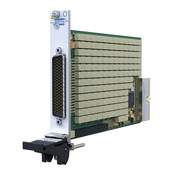
Supported by PXI or LXI Chassis y Supported by BIRST ™ and eBIRST ™ Test Tools y 3 Year Warranty The 40-518A is a 16x8, 2-pole, 2 A matrix module and is part Built-In Relay Self-Test - BIRST of our range PXI switching solutions. - Page 10 Max Switch Voltage: 300 VDC/250 VAC* Note: The pinout for the 40-518A differs from the 40-518, Max Power: 62.5 VA, 60 W from 30 V to see the user manual for details.
- Page 11 Please contact your local sales office to discuss. For further assistance, please contact your local Pickering sales office. Mating Connectors & Cabling For connection accessories for the 40-518A please refer to the 90-006D 78-pin D-type Connector Accessories data sheet where a complete list and documentation can be found for accessories, or refer to the Connection Solutions catalog.
- Page 12 We provide a full range of supporting cable and connector solutions for all our switching products—20 connector families with 1200+ products. We offer everything from simple mating connectors to complex cables assemblies and terminal blocks. All assemblies are manufactured by Pickering and are guaranteed to mechanically and electrically mate to our modules. Connectors & Backshells...
- Page 13 2 A 2-Pole Matrix, 40-518A Programming Pickering provide kernel, IVI and VISA (NI & Keysight) drivers which are compatible with all Microsoft supported versions of Windows and popular older versions. For a list of all supporting operating systems, please see: pickeringtest.com/os...
- Page 14 SECTION 1 - TECHNICAL SPECIFICATION pickering THIS PAGE INTENTIONALLY BLANK 2 A 2-POLE MATRIX MODULE 40-518A Page 1.6...
-
Page 15: Functional Description
U1 is configured by the EEPROM U2. PCI Bridge Configuration BIRST Module Terminating Configuration Resistors R1-14 Relays RL1-128 Relay Drivers 16x8, 2-pole Matrix +12V U11-18 +3.3V Figure 2.1 - 40-518A Matrix Module: Functional Block Diagram 2 A 2-POLE MATRIX MODULE 40-518A Page 2.1... - Page 16 SECTION 2 - TECHNICAL DESCRIPTION pickering THIS PAGE INTENTIONALLY BLANK 2 A 2-POLE MATRIX MODULE 40-518A Page 2.2...
-
Page 17: Installation
VII. à la Page VII. Ensure that there is adequate ventilation. Assurez-vous que la ventilation est adéquate. 2 A 2-POLE MATRIX MODULE 40-518A REED RELAY MODULE 40-110/115/120/125 Page 3.1 Page 3.1... - Page 18 9. For Pickering Interfaces modular LXI installation b. Pour un système comprenant plus d’un châssis, there is no requirement to use any particular power allumez le dernier châssis dans le système up sequence.
-
Page 19: Software Installation
Si vous n’êtes pas un utilisateur de LabVIEW, vous LabVIEW Runtime Engine installer via the shortcut devez choisir la version “complète”, et une fois qu’elle on the Programs>>Pickering menu. In the absence of a été installée. Lancer le programme d’installation LabVIEW the Runtime Engine is required to support LabVIEW Runtime Engine via le raccourci dans the Pickering Test Panels application. -
Page 20: Testing Operation
Figure 3.2 - General Soft Front Panel Icon A selector panel will appear, listing all installed Pickering PCI, PXI or LXI switch cards and resistor cards. Click on the card you wish to control, and a graphical control panel is presented allowing operation of the card. -
Page 21: Programming Guide
SECTION 4 - PROGRAMMING GUIDE PROGRAMMING OPTIONS FOR PICKERING INTERFACES PXI MODULES For information on the installation and use of drivers and the programming of Pickering’s products in various software environments, please refer to the Software User Manual. This is available as a download from: https://www.pickeringtest.com/support/software-drivers-and-downloads... -
Page 22: Module Architecture
MODULE ARCHITECTURE The 40-518A is a two pole switching matrix with 128 crosspoints.Connections are made by operating the relays at the crosspoints between X and Y lines allowing single X-Y connections, or X-X connections using a Y line as a path. -
Page 23: Programming The Module
PROGRAMMING THE MODULE Using The IVI Driver, Direct I/O Driver or VISA Driver This section provides some code fragments which show how to control the 40-518A-002 Matrix using the IVI Driver, Direct I/O Driver or the VISA Driver. Once the drivers are installed the manual “Sys40Prg.pdf” and driver help files which fully describes these functions can be found in the Pickering folder(s) or the Pickering entries on your Start Menu. - Page 24 SECTION 4 - PROGRAMMING GUIDE pickering THIS PAGE INTENTIONALLY BLANK 2 A 2-POLE MATRIX MODULE 40-518A Page 4.4...
-
Page 25: Connector Information
Y3.2 Y6.1 Y5.1 Y6.2 Y5.2 Y8.1 Y7.1 Y8.2 Y7.2 FP_GND FP_GND Figure 5.1 - 2 Amp 2 Pole Matrix Module 40-518A-002 (16x8): Pinouts (78-pin Male D-type Connector Viewed From Front of Module) 2 A 2-POLE MATRIX MODULE 40-518A Page 5.1... - Page 26 SECTION 5 - CONNECTOR INFORMATION pickering THIS PAGE INTENTIONALLY BLANK 2 A 2-POLE MATRIX MODULE 40-518A Page 5.2...
-
Page 27: Trouble Shooting
Mises en garde au début du manuel. INSTALLATION PROBLEMS PROBLÈMES D’INSTALLATION The Plug & Play functionality of Pickering switch cards La fonctionnalité Plug & Play des cartes de generally ensures trouble-free installation. commutation Pickering assure généralement une installation sans problème. -
Page 28: Maintenance Information
OUTILS DE TEST DE SYSTEME DE SWITCHING SYSTEM TEST TOOLS COMMUTATION Please refer to Section 7 - Maintenance Information Référez-vous à la Section 7 - Information sur l’entretien REED RELAY MODULE 40-110/115/120/125 2 A 2-POLE MATRIX MODULE 40-518A Page 6.2 Page 6.2... - Page 29 Pour les modules PXI qui sont pris en charge dans Pickering Interfaces’ Modular LXI Chassis (such l’un des châssis modulaire LXI de Pickering Interfaces as the 60-102B and 60-103B) no module software (comme le 60-102B et 60-103B) aucune mise à jour update is required.
-
Page 30: Relay Lookup Tables
USING BIRST ™ (BUILT-IN RELAY SELF TEST) UTILISATION BIRST ™ (AUTOTEST INTÉGRÉ DE RELAIS) The Pickering Interfaces BIRST (Built-In Relay Self Test) Tool provides a simple means of testing selected L’outil d’autotest intégré de relais BIRST™ de Pickering Interfaces switching products, including... - Page 31 SECTION 7 - MAINTENANCE INFORMATION pickering TABLE 7.1 - 40-518A-002 Matrix Module: Relay Numbering 40-518A RELAY CROSS REFERENCE (16x8 MATRIX) Crosspoint Crosspoint Crosspoint Crosspoint Relay Relay Relay Relay 1.1 & 1.2 1.1 & 1.2 1.1 & 1.2 3.1 & 3.2 RL33 1.1 &...
- Page 32 RL81 RL82 RL83 RL84 RL85 RL86 RL87 RL88 RL127 RL89 RL90 RL91 RL92 RL93 RL94 RL95 RL96 RL128 BIRST BIRST RELAY RELAY SPARE Figure 7.1 - 16x8 Matrix Module 40-518A-002: Component Layout 2 A 2-POLE MATRIX MODULE 40-518A Page 7.4...
Need help?
Do you have a question about the 40-518A and is the answer not in the manual?
Questions and answers