
Related Manuals for Pickering PXI 30 A


Summary of Contents for Pickering PXI 30 A
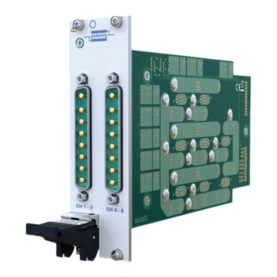
- Page 1 40-555A User Manual PXI 30 A Solid State Matrix Module pickeringtest.com Issue 1.1 November 2021...
- Page 2 © COPYRIGHT (2021) PICKERING INTERFACES. ALL RIGHTS RESERVED. No part of this publication may be reproduced, transmitted, transcribed, translated or stored in any form, or by any means without the written permission of Pickering Interfaces. Technical details contained within this publication are subject to change without notice.
- Page 3 Pickering Interfaces strives to fulfil all relevant environmental laws and regulations and reduce wastes and releases to the environment. Pickering Interfaces aims to design and operate products in a way that protects the environment and the health and safety of its employees, customers and the public. Pickering Interfaces endeavours to develop and manufacture products that can be produced, distributed, used and recycled, or disposed of, in a safe and environmentally friendly manner.
-
Page 4: Product Safety
PRODUCT SAFETY SAFETY SYMBOLS The following safety symbols may be used on the product and throughout the product documentation. MEANING / DESCRIPTION SYMBOL PROTECTIVE EARTH (GROUND) To identify any terminal which is intended for connection to an external conductor for protection against electric shock in case of a fault, or the terminal of a protective earth (ground) electrode. -
Page 5: Table Of Contents
CONTENTS Copyright Statement ..............II Technical Support and Warranty ..........III Product Safety ................IV Contents (this page) ..............V Warnings and Cautions ..............VII Section 1 Technical Specification ...............1.1 Section 2 Technical Description ..............2.1 Functional Description ............2.1 Section 3 Installation ..................3.1 Pre Operation Checks ............3.1 Hardware Installation ............3.2... - Page 6 THIS PAGE INTENTIONALLY BLANK 30A SOLID STATE MATRIX 40-555A Page (VI)
-
Page 7: Warnings And Cautions
Not to be used in safety critical circuits, refer to the Pickering Interfaces’ terms & conditions of sale. This module must not be used for the switching of Mains Circuits. For the switching of voltages up to the module’s full specification, Secondary Circuit power supplies and the Device Under Test must... - Page 8 CAUTION - PRODUCT DOCUMENTATION SYMBOL Suitably qualified & trained users should ensure that the accompanying documentation is fully read and understood before attempting to install or operate the product. SAFETY INSTRUCTIONS SAFETY INSTRUCTIONS All cleaning and servicing requires the equipment to be isolated and disconnected from the power source and user I/O signals (refer to the Maintenance Section).
-
Page 9: Technical Specification
SECTION 1 - TECHNICAL SPECIFICATION pickering PXI 30 A Solid State Matrix Module 40-555A SECTION 1 - TECHNICAL SPECIFICATION y 8x2 Power Matrix y 30 A Rating at 40 V y 40 A Rating For Single Relay Closure y Very High Hot Switch Capacity... - Page 10 Specification reflects test conditions in a Pickering PXI chassis. Refer to supplier for chassis cooling capacity, restrict average RMS current over 5 minute period to 25A per channel for chassis meeting the minimum PXI recommendations.
- Page 11 This product is supported by the eBIRST test tools which Product Customization simplify the identification of failed relays, the required Pickering modules are designed and manufactured on our eBIRST tools are below. This product requires master own flexible manufacturing lines, giving complete product...
- Page 12 We provide a full range of supporting cable and connector solutions for all our switching products—20 connector families with 1200+ products. We offer everything from simple mating connectors to complex cables assemblies and terminal blocks. All assemblies are manufactured by Pickering and are guaranteed to mechanically and electrically mate to our modules. Connectors & Backshells...
- Page 13 30 A Solid State Matrix, 40-555A Programming Pickering provide kernel, IVI and VISA (NI & Keysight) drivers which are compatible with all Microsoft supported versions of Windows and popular older versions. For a list of all supporting operating systems, please see: pickeringtest.com/os...
- Page 14 SECTION 1 - TECHNICAL SPECIFICATION pickering THIS PAGE INTENTIONALLY BLANK 30A SOLID STATE MATRIX 40-555A Page 1.6...
-
Page 15: Functional Description
SECTION 2 - TECHNICAL DESCRIPTION pickering SECTION 2 - TECHNICAL DESCRIPTION FUNCTIONAL DESCRIPTION A functional block diagram is provided in Figure 2.1. The Matrix Module is powered by +5V and +3.3V inputs via Compact PCI connector J1. The interface to the user test equipment is via the front panel mounted 8-pin D-type connectors. - Page 16 SECTION 2 - TECHNICAL DESCRIPTION pickering THIS PAGE INTENTIONALLY BLANK 30A SOLID STATE MATRIX 40-555A Page 2.2...
-
Page 17: Installation
Modular products require installation in a suitable PXI/LXI chassis. The module is designed for indoor use only. PREOPERATION CHECKS (UNPACKING) 1. Check the module for transport damage and report any damage immediately to Pickering Interfaces. Do not attempt to install the product if any damage is evident. -
Page 18: Hardware Installation
For a system comprising more than one chassis, turn ON the last chassis in the system followed by the penultimate, etc, and finally turn ON the external controller or chassis containing the system controller. 9. For Pickering Interfaces modular LXI installation there is no requirement to use any particular power up sequence. -
Page 19: Testing Operation
Figure 3.2 - General Soft Front Panel Icon A selector panel will appear, listing all installed Pickering PCI, PXI or LXI switch cards and resistor cards. Click on the card you wish to control, and a graphical control panel is presented allowing operation of the card. - Page 20 SECTION 3 - INSTALLATION pickering THIS PAGE INTENTIONALLY BLANK 30A SOLID STATE MATRIX 40-555A Page 3.4...
-
Page 21: Programming Guide
SECTION 4 - PROGRAMMING Programming options for Pickering Interfaces PXI Modules For information on the installation and use of drivers and the programming of Pickering’s products in various software environments, please refer to the Software User Manual. This is available as a download from: https://www.pickeringtest.com/support/software-drivers-and-downloads... -
Page 22: Programming The Solid State Matrix
SECTION 4 - PROGRAMMING GUIDE pickering Programming The Solid State Matrix The 40-555A is a single pole switching matrix with 8 connections on the X-axis and 2 connections on the Y-axis. Connections are made by operating the relays at the crosspoints between X and Y lines allowing single X-Y connections, or X-X connections using a Y line as a path. -
Page 23: Using Ivi Driver, Direct Driver Or Visa Driver
Once the drivers are installed the manual “Sys40Prg.pdf” and driver help files which fully describes these functions can be found in the Pickering folder(s) or the Pickering entries on your Start Menu. The card must be opened before use and closed after using the following function calls: Direct I/O Driver - Open with PIL_OpenCards or PIL_OpenSpecifiedCard and close with PIL_CloseCards or PIL_CloseSpecifiedCards respectively. - Page 24 SECTION 4 - PROGRAMMING GUIDE pickering THIS PAGE INTENTIONALLY BLANK 30A SOLID STATE MATRIX 40-555A Page 4.4...
- Page 25 SECTION 5 - CONNECTOR INFORMATION pickering SECTION 5 - CONNECTOR INFORMATION pickering X5 X6 X7 X8 Figure 5.1 - 8x2 30A Solid State Matrix 40-555A: Pinouts Viewed From Front Panel, Connectors are 8-pin Power D-type Plugs. 30A SOLID STATE MATRIX 40-555A...
- Page 26 SECTION 5 - CONNECTOR INFORMATION pickering THIS PAGE INTENTIONALLY BLANK 30A SOLID STATE MATRIX 40-555A Page 5.2...
-
Page 27: Troubleshooting
PCI configuration, highlighting any potential configuration problems. Specific details of all installed Pickering switch cards are included. All the installed Pickering switch cards should be listed in the “Pilpxi information” section - if one or more cards is missing it may be possible to determine the reason by referring to the PCI configuration dump contained in the report, but interpretation of this information is far from straightforward, and the best course is to contact Pickering support: support@pickeringtest.com, if possible... - Page 28 SECTION 6 - TROUBLE SHOOTING pickering THIS PAGE INTENTIONALLY BLANK 30A SOLID STATE MATRIX 40-555A Page 6.2...
-
Page 29: Relay Look-Up Tables
For PXI modules which are supported in one of Pickering Interfaces’ Modular LXI Chassis (such as the 60-102B and 60-103B) no module software update is required. If the module was introduced after the LXI chassis was manufactured the module may not be recognized, in this case the chassis firmware may need upgrading. - Page 30 SECTION 7 - MAINTENANCE INFORMATION pickering RELAY LOOK-UP TABLE The relays are fitted on two daugter PCBs, designated inner and outer, both have the same relay positioning. 40-555A RELAY CROSS REFERENCE Crosspoint Daughter Relay Board U11 & U12 U5 & U6 U15 &...
- Page 31 SECTION 7 - MAINTENANCE INFORMATION pickering Figure 7.1 - 40-555A Component Layout - Daughter Board 30A SOLID STATE MATRIX 40-555A Page 7.3...
- Page 32 SECTION 7 - MAINTENANCE INFORMATION pickering THIS PAGE INTENTIONALLY BLANK 30A SOLID STATE MATRIX 40-555A Page 7.4...
Need help?
Do you have a question about the PXI 30 A and is the answer not in the manual?
Questions and answers