
Related Manuals for Pickering 40-582


Summary of Contents for Pickering 40-582
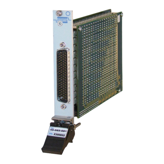
- Page 1 User Manual 2 Amp 2-Pole High Density Matrix Module With BIRST™ (Model No. 40-582) Issue 4.2 April 2017 pickeringtest.com pickering 2 AMP 2-POLE HIGH DENSITY MATRIX 40-582 Page (1)
- Page 2 © COPYRIGHT (2017) PICKERING INTERFACES. ALL RIGHTS RESERVED. No part of this publication may be reproduced, transmitted, transcribed, translated or stored in any form, or by any means without the written permission of Pickering Interfaces. Technical details contained within this publication are subject to change without notice.
- Page 3 Pickering Interfaces strives to fulfil all relevant environmental laws and regulations and reduce wastes and releases to the environment. Pickering Interfaces aims to design and operate products in a way that protects the environment and the health and safety of its employees, customers and the public. Pickering Interfaces endeavours to develop and manufacture products that can be produced, distributed, used and recycled, or disposed of, in a safe and environmentally friendly manner.
-
Page 4: Product Safety
If this product is heavy reference should be made to the safety instructions for provisions of lifting and moving. STATIC SENSITIVE To indicate that static sensitive devices are present and handling precautions should be followed. REED RELAY MODULE 40-110/115/120/125 2 AMP 2-POLE HIGH DENSITY MATRIX 40-582 Page (IV) Page (IV) -
Page 5: Table Of Contents
Using IVI Driver, Direct I/O Driver or VISA Driver ....4.4 Section 5 Connector Information ..............5.1 Section 6 Troubleshooting ................6.1 Section 7 Maintenance Information ............7.1 Switching System Test Tools ..........7.1 Relay Look-Up Tables ............7.1 2 AMP 2-POLE HIGH DENSITY MATRIX 40-582 Page (V) - Page 6 THIS PAGE INTENTIONALLY BLANK 2 AMP 2-POLE HIGH DENSITY MATRIX 40-582 Page (VI)
-
Page 7: Warnings And Cautions
Unused slots in the PXI/LXI chassis are populated with blanking plates to prevent access to user I/O signals that may be present. Blanking panels are available to order from Pickering in a variety of slot widths. If the product is not used in this manner for example by using an extender card then additional care must be taken to avoid contact with exposed signals. - Page 8 THIS PAGE INTENTIONALLY BLANK 2 AMP 2-POLE HIGH DENSITY MATRIX 40-582 Page (VIII)
-
Page 9: Technical Specification
● Built-In Diagnostics - BIRST ● Supported by eBIRST ● 3 Year Warranty The 40-582 is a 256 crosspoint PXI matrix with dual pole switching. The module consists of a 16x16 matrix of 2-pole electro-mechanical relays with 2A current handling. - Page 10 For further assistance, please contact your local Pickering sales office. Power Requirements Mating Connectors & Cabling +3.3V +12V -12V For connection accessories for the 40-582 module please 500mA (typical) 130mA (typical) 70mA (typical) refer to the 90-006D 78-pin D-type Connector Accessories...
- Page 11 All modules are fully CE compliant and meet applicable EU Systems such as LabVIEW RT. For other RTOS support directives: Low-voltage safety EN61010-1:2001, contact Pickering. These drivers may be used with a variety of EMC Immunity EN61000-6-1:2001, Emissions EN55011:1998. programming environments and applications including: —...
- Page 12 SECTION 1 - TECHNICAL SPECIFICATION pickering THIS PAGE INTENTIONALLY BLANK 2 AMP 2-POLE HIGH DENSITY MATRIX 40-582 Page 1.4...
-
Page 13: Technical Description
RL129 to RL256 BRIDGE TERMINATING RESISTORS RELAY R1 TO R12 DRIVERS U19 to U26 +3.3V PCI BRIDGE VOLTAGE CONFIGURATION +2.5V REGULATOR Figure 2.1 - 2 Amp 2-Pole Matrix Module 40-582: Functional Block Diagram 2 AMP 2-POLE HIGH DENSITY MATRIX 40-582 Page 2.1... - Page 14 SECTION 2 - TECHNICAL DESCRIPTION pickering THIS PAGE INTENTIONALLY BLANK 2 AMP 2-POLE HIGH DENSITY MATRIX 40-582 Page 2.2...
-
Page 15: Installation
Modular products require installation in a suitable PXI/LXI chassis. The module is designed for indoor use only. PREOPERATION CHECKS (UNPACKING) 1. Check the module for transport damage and report any damage immediately to Pickering Interfaces. Do not attempt to install the product if any damage is evident. -
Page 16: Hardware Installation
For a system comprising more than one chassis, turn ON the last chassis in the system followed by the penultimate, etc, and finally turn ON the external controller or chassis containing the system controller. 9. For Pickering Interfaces modular LXI installation there is no requirement to use any particular power up sequence. -
Page 17: Testing Operation
Figure 3.2 - General Soft Front Panel Icon A selector panel will appear, listing all installed Pickering PCI, PXI or LXI switch cards and resistor cards. Click on the card you wish to control, and a graphical control panel is presented allowing operation of the card. - Page 18 SECTION 3 - INSTALLATION pickering THIS PAGE INTENTIONALLY BLANK 2 AMP 2-POLE HIGH DENSITY MATRIX 40-582 Page 3.4...
-
Page 19: Programming Guide
IVI Driver for Windows - pi40iv The pi40iv IVI (Interchangeable Virtual Instrument) driver supports all Pickering Interfaces PXI switch cards that are consistent with the Iviswtch class model - as are the great majority of cards in the System 40/45/50 ranges. It integrates well with LabWindows/CVI and LabVIEW, and is fully compatible with Switch Executive. - Page 20 Pickering LXI products include an SSH interface which allows remote command line access to control cards, or, using a suitable package, programmatic control. The user is advised to visit the Pickering web site for further details of all the above drivers, where documentation, example programs, and further help with driver choice are available.
- Page 21 Programming The Very High Density Matrix The 40-582 is a two pole switching matrix with 16 connections on the X-axis and 16 connections on the Y-axis. Connections are made by operating the relays at the crosspoints between X and Y lines allowing single X-Y connections, or X-X connections using a Y line as a path.
-
Page 22: Using Ivi Driver, Direct I/O Driver Or Visa Driver
Once the drivers are installed the manual “Sys40Prg.pdf” and driver help files which fully describes these functions can be found in the Pickering folder(s) or the Pickering entries on your Start Menu. The card must be opened before use and closed after using the following function calls: Direct I/O driver - Open with PIL_OpenCards or PIL_OpenSpecifiedCard and close with PIL_CloseCards or PIL_CloseSpecifiedCards respectively. -
Page 23: Connector Information
Y14.1 Y13.2 Y14.2 Y15.1 Y16.1 Y15.2 Y16.2 FP_GND FP_GND Figure 5.1 - 2 Amp 2-Pole 16x16 Matrix Module 40-582-001: 78-pin D-type Front Panel Male Connector Pinout. (Viewed From Front of Module) 2 AMP 2-POLE HIGH DENSITY MATRIX 40-582 Page 5.1... - Page 24 SECTION 5 - CONNECTOR INFORMATION pickering THIS PAGE INTENTIONALLY BLANK 2 AMP 2-POLE HIGH DENSITY MATRIX 40-582 Page 5.2...
-
Page 25: Troubleshooting
PCI configuration, highlighting any potential configuration problems. Specific details of all installed Pickering switch cards are included. All the installed Pickering switch cards should be listed in the “Pilpxi information” section - if one or more cards is missing it may be possible to determine the reason by referring to the PCI configuration dump contained in the report, but interpretation of this information is far from straightforward, and the best course is to contact Pickering support: support@pickeringtest.com, if possible... - Page 26 SECTION 6 - TROUBLE SHOOTING pickering THIS PAGE INTENTIONALLY BLANK 2 AMP 2-POLE HIGH DENSITY MATRIX 40-582 Page 6.2...
-
Page 27: Relay Look-Up Tables
The Pickering Interfaces BIRST (Built-In Relay Self Test) Tool provides a simple means of testing selected Pickering Interfaces switching products, including this model. The tool can be used to find relay faults or to provide confirmation that a product is operating correctly, either as part of the regular system calibration or because a system fault is suspected and the switch system needs to be eliminated from the fault finding procedure. - Page 28 SECTION 7 - MAINTENANCE INFORMATION pickering 40-582 RELAY CROSS REFERENCE - MOTHER BOARD Crosspoint Crosspoint Crosspoint Crosspoint Relay Relay Relay Relay 1.1 & 1.2 1.1 & 1.2 1.1 & 1.2 3.1 & 3.2 RL33 1.1 & 1.2 5.1 & 5.2 RL65 1.1 &...
- Page 29 SECTION 7 - MAINTENANCE INFORMATION pickering 40-582 RELAY CROSS REFERENCE - DAUGHTER BOARD Crosspoint Crosspoint Crosspoint Relay Relay Relay 1.1 & 1.2 9.1 & 9.2 RL129 1.1 & 1.2 12.1 & 12.2 RL177 1.1 & 1.2 15.1 & 15.2 RL225 2.1 &...
- Page 30 SECTION 7 - MAINTENANCE INFORMATION pickering Figure 7.1 - 40-582 Component Layout - Mother Board 2 AMP 2-POLE HIGH DENSITY MATRIX 40-582 Page 7.4...
- Page 31 RL163 RL179 RL195 RL211 RL227 RL243 RL130 RL146 RL162 RL178 RL194 RL210 RL226 RL242 RL129 RL145 RL161 RL177 RL193 RL209 RL225 RL241 Figure 7.2 - 40-582 Component Layout - Daughter Board 2 AMP 2-POLE HIGH DENSITY MATRIX 40-582 Page 7.5...
- Page 32 SECTION 7 - MAINTENANCE INFORMATION pickering THIS PAGE INTENTIONALLY BLANK 2 AMP 2-POLE HIGH DENSITY MATRIX 40-582 Page 7.6...
Need help?
Do you have a question about the 40-582 and is the answer not in the manual?
Questions and answers