
Related Manuals for Pickering BRIC 40-565B


Summary of Contents for Pickering BRIC 40-565B
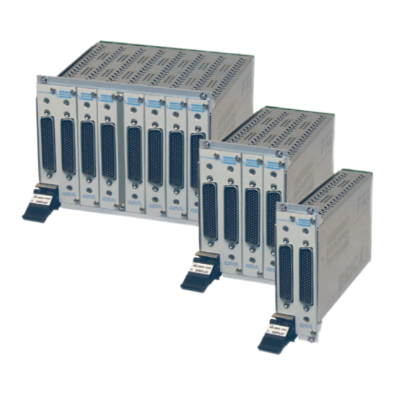
- Page 1 40-565B User Manual PXI 2 Amp BRIC™ Multi-Slot Matrix Module pickeringtest.com Issue 3.6 February 2020...
- Page 2 © COPYRIGHT (2021) PICKERING INTERFACES. ALL RIGHTS RESERVED. No part of this publication may be reproduced, transmitted, transcribed, translated or stored in any form, or by any means without the written permission of Pickering Interfaces. Technical details contained within this publication are subject to change without notice.
- Page 3 Pickering Interfaces strives to fulfil all relevant environmental laws and regulations and reduce wastes and releases to the environment. Pickering Interfaces aims to design and operate products in a way that protects the environment and the health and safety of its employees, customers and the public. Pickering Interfaces endeavours to develop and manufacture products that can be produced, distributed, used and recycled, or disposed of, in a safe and environmentally friendly manner.
-
Page 4: Product Safety
PRODUCT SAFETY SAFETY SYMBOLS The following safety symbols may be used on the product and throughout the product documentation. MEANING / DESCRIPTION SYMBOL PROTECTIVE EARTH (GROUND) To identify any terminal which is intended for connection to an external conductor for protection against electric shock in case of a fault, or the terminal of a protective earth (ground) electrode. -
Page 5: Table Of Contents
CONTENTS Copyright Statement ..............II Technical Support and Warranty ..........III Product Safety ................IV Contents (this page) ..............V Warnings and Cautions .............. VII Section 1 Technical Specification ............... 1.1 Section 2 Technical Description ..............2.1 Mechanical Description ............2.1 Functional Description ............ - Page 6 THIS PAGE INTENTIONALLY BLANK BRIC INTEGRATED PXI 2-AMP MATRIX WITH BIRST™ (40-565B) Page (VI)
-
Page 7: Warnings And Cautions
Not to be used in safety critical circuits, refer to the Pickering Interfaces’ terms & conditions of sale. This module must not be used for the switching of Mains Circuits. For the switching of voltages up to the module’s full specification, Secondary Circuit power supplies and the Device Under Test must... - Page 8 CAUTION - PRODUCT DOCUMENTATION SYMBOL Suitably qualified & trained users should ensure that the accompanying documentation is fully read and understood before attempting to install or operate the product. SAFETY INSTRUCTIONS SAFETY INSTRUCTIONS All cleaning and servicing requires the equipment to be isolated and disconnected from the power source and user I/O signals (refer to the Maintenance Section).
-
Page 9: Technical Specification
Supported by PXI or LXI Chassis y Supported by BIRST ™ and eBIRST ™ Test Tools The 2 A Matrix BRIC is a higher power/voltage version of Pickering’s established range of PXI Matrix BRIC y 3 Year Warranty modules. It features higher voltage, current and power handling than the ultra high density reed relay based BRICs. - Page 10 2 A BRIC Multi-Slot Matrix, 40-565B 40-565B BRIC Key Advantages • Pickering Introduced the original BRIC back in 2003, the 40-565B is an update to the original, well proven 40-565 intoduced in 2004. • Complete PXI Switching Solution in one PXI Module.
- Page 11 SECTION 1 - TECHNICAL SPECIFICATION pickering Overview 2 A BRIC Multi-Slot Matrix, 40-565B The 40-565B in BRIC2 Format is Available With Matrix Configurations of 29x8 or 58x8 (2-Pole) X116 The 40-565B in BRIC4 Format is Available With Matrix Configurations Between 29x8 and 116x8 (2-Pole)
- Page 12 Discovering the source of the problem takes time and effort users may not have when working to tight schedules. To ensure low cost of ownership, Pickering Interfaces has now incorporated a test tool, BIRST, into the BRIC. BIRST The BIRST is a sophisticated diagnostic tool, which allows a complete relay self test of a BRIC module.
- Page 13 PCB when the change is made, especially if the relays are surface mount devices. Pickering has greatly improved the test methodology to the extent it is now possible to include full self test in PXI switch modules with minimal impact on cost and switching density, welcome news for users who are used to having such features in their solutions.
- Page 14 SECTION 1 - TECHNICAL SPECIFICATION pickering Specifications 2 A BRIC Multi-Slot Matrix, 40-565B Power Requirements Relay Type The 40-565B BRIC modules are fitted with electro- +3.3V +12V -12V mechanical relays. 60m A 1.1 A max (BRIC2) 30 mA General Switching Specification (typical) 2.1 A max (BRIC4)
- Page 15 2 A 2-Pole 203x8 Matrix 40-565B-102-203x8 2 A 2-Pole 232x8 Matrix 40-565B-102-232x8 For further assistance, please contact your local Pickering sales office. For the expansion of an existing BRIC matrix or replacement of faulty BRIC daughter cards please contact Mating Connectors & Cabling your local sales office.
- Page 16 We provide a full range of supporting cable and connector solutions for all our switching products—20 connector families with 1200+ products. We offer everything from simple mating connectors to complex cables assemblies and terminal blocks. All assemblies are manufactured by Pickering and are guaranteed to mechanically and electrically mate to our modules. Connectors & Backshells...
- Page 17 2 A BRIC Multi-Slot Matrix, 40-565B Programming Pickering provide kernel, IVI and VISA (NI & Keysight) drivers which are compatible with all Microsoft supported versions of Windows and popular older versions. For a list of all supporting operating systems, please see: pickeringtest.com/os...
- Page 18 SECTION 1 - TECHNICAL SPECIFICATION pickering THIS PAGE INTENTIONALLY BLANK BRIC INTEGRATED PXI 2-AMP MATRIX WITH BIRST™ (40-565B) Page 1.10...
-
Page 19: Technical Description
SECTION 2 - TECHNICAL DESCRIPTION pickering SECTION 2 - TECHNICAL DESCRIPTION MECHANICAL DESCRIPTION The BRIC Module comprises an alloy chassis, 2 slot (2 sub-cards), 4 slot (4 sub-cards) or 8 slot (8 sub-cards) width, with an integral backplane and a number of High Density Sub-Matrix Cards. The chassis is provided with cooling slots, top and bottom. - Page 20 SECTION 2 - TECHNICAL DESCRIPTION pickering Front Panel 78-pin D-type Connector ANALOG BACKPLANE Isolation MATRIX CARD 1 Switches Front Panel 78-pin D-type Connector Isolation MATRIX CARD 2 Switches Front Panel 78-pin D-type Connector X204 X232 Isolation MATRIX CARD 8 Switches Figure 2.2 - 40-565B BRIC Module: Switching Architecture...
- Page 21 SECTION 2 - TECHNICAL DESCRIPTION pickering 4-SLOT BACKPLANE MOTHER BOARD Y BUS Y ISOLATION RELAYS RELAY MATRIX COILS EEPROM X BUS RELAY DRIVERS U1 TO U10 CONTROL Y BUS Y BUS CONTROL RELAY MATRIX COILS RELAY DRIVERS U11 TO U20...
- Page 22 SECTION 2 - TECHNICAL DESCRIPTION pickering THIS PAGE INTENTIONALLY BLANK BRIC INTEGRATED PXI 2-AMP MATRIX WITH BIRST™ (40-565B) Page 2.4...
-
Page 23: Installation
Modular products require installation in a suitable PXI/LXI chassis. The module is designed for indoor use only. PREOPERATION CHECKS (UNPACKING) 1. Check the module for transport damage and report any damage immediately to Pickering Interfaces. Do not attempt to install the product if any damage is evident. -
Page 24: Hardware Installation
For a system comprising more than one chassis, turn ON the last chassis in the system followed by the penultimate, etc, and finally turn ON the external controller or chassis containing the system controller. 9. For Pickering Interfaces modular LXI installation there is no requirement to use any particular power up sequence. -
Page 25: Testing Operation
Figure 3.2 - General Soft Front Panel Icon A selector panel will appear, listing all installed Pickering PCI, PXI or LXI switch cards and resistor cards. Click on the card you wish to control, and a graphical control panel is presented allowing operation of the card. - Page 26 SECTION 3 - INSTALLATION pickering THIS PAGE INTENTIONALLY BLANK BRIC INTEGRATED PXI 2-AMP MATRIX WITH BIRST™ (40-565B) Page 3.4...
-
Page 27: Programming Guide
SECTION 4 - PROGRAMMING PROGRAMMING OPTIONS FOR PICKERING INTERFACES PXI MODULES For information on the installation and use of drivers and the programming of Pickering’s products in various software environments, please refer to the Software User Manual. This is available as a download from: https://www.pickeringtest.com/support/software-drivers-and-downloads... -
Page 28: Module Architecture
SECTION 4 - PROGRAMMING GUIDE pickering MODULE ARCHITECTURE The 40-565B is a high density 2-pole switching matrix constructed from 29x8 sub-matrix cards linked with an analog backplane. The 40-565B module can be fitted with 1 or 2 sub-matrix cards (BRIC2), between 1 & 4 sub-matrix cards (BRIC4) or between 1 &... -
Page 29: Programming The Module - Standard Version
Once the drivers are installed the manual “Sys40Prg.pdf” and driver help files which fully describes these functions can be found in the Pickering folder(s) or the Pickering entries on your Start Menu. The card must be opened before use and closed after using the following function calls: Direct I/O Driver - Open with PIL_OpenCards or PIL_OpenSpecifiedCard and close with PIL_CloseCards or PIL_CloseSpecifiedCards respectively. -
Page 30: Programming The Module - Independent Isolation
Backplane Isolation Switches - 8 for each sub-matrix fitted (64 for a fully populated BRIC8) Setting an X to Y Signal Path Using The Direct I/O Driver or VISA Driver: Using the Pickering Direct I/O Driver: DWORD sub_unit = 1; //Matrix PIL_ClearSub(CardNo, sub_unit);... - Page 31 SECTION 4 - PROGRAMMING GUIDE pickering SUB-UNIT 2 SUB-UNIT 1 Backplane 232x8 Matrix (X1-Y1 to X232-Y8) Isolation FRONT PANEL CONNECTOR ANALOG BACKPLANE Bit 1 Bit 2 Bit 3 Bit 4 Bit 5 Bit 6 Bit 7 Bit 8 SUB-MATRIX CARD 1...
- Page 32 SECTION 4 - PROGRAMMING GUIDE pickering Using the IVI Driver The IVI driver assigns names to each channel or node. To program the 40-565B BRIC matrix from the IVI driver it is necessary to know the name of these channels. The channel naming for the matrix is shown in Table 4.2 and the channel naming for the isolation switches is shown in Table 4.3.
- Page 33 SECTION 4 - PROGRAMMING GUIDE pickering TABLE 4.3 - Backplane Y Isolation Switces, IVI Driver Naming (Independent Isolation Version) IVI Channel Sub-Matrix IVI Channel Sub-Matrix Function Function Name Card No. Name Card No. Connects Y1 Connects Y1 comB1, chB1 comB33, chB33 to backplane “Y1”...
- Page 34 SECTION 4 - PROGRAMMING GUIDE pickering THIS PAGE INTENTIONALLY BLANK BRIC INTEGRATED PXI 2-AMP MATRIX WITH BIRST™ (40-565B) Page 4.8...
-
Page 35: Connector Information
SECTION 5 - CONNECTOR INFORMATION pickering SECTION 5 - CONNECTOR INFORMATION Figures 5.1 shows the connector positioning for the 40-565B Matrix Module. Figures 5.2 to 5.9 provide the pinouts for the 78-pin D-type connectors on the individual matrix cards. In its minimum configuration, the matrix has a single matrix card in position 1. - Page 36 SECTION 5 - CONNECTOR INFORMATION pickering X2.2 X31.2 X1.2 X30.2 X2.1 X31.1 X1.1 X30.1 X4.2 X33.2 X3.2 X32.2 X3.1 X4.1 X32.1 X33.1 X6.2 X35.2 X5.2 X34.2 X6.1 X35.1 X5.1 X34.1 X8.2 X37.2 X7.2 X36.2 X7.1 X8.1 X36.1 X37.1 X10.2 X39.2 X9.2...
- Page 37 SECTION 5 - CONNECTOR INFORMATION pickering X118.2 X147.2 X117.2 X146.2 X118.1 X147.1 X117.1 X146.1 X120.2 X149.2 X119.2 X148.2 X119.1 X120.1 X148.1 X149.1 X122.2 X151.2 X121.2 X150.2 X122.1 X151.1 X121.1 X150.1 X124.2 X153.2 X123.2 X152.2 X124.1 X153.1 X123.1 X152.1 X126.2 X155.2 X125.2...
- Page 38 SECTION 5 - CONNECTOR INFORMATION pickering THIS PAGE INTENTIONALLY BLANK BRIC INTEGRATED PXI 2-AMP MATRIX WITH BIRST™ (40-565B) Page 5.4...
-
Page 39: Trouble Shooting
PCI configuration, highlighting any potential configuration problems. Specific details of all installed Pickering switch cards are included. All the installed Pickering switch cards should be listed in the “Pilpxi information” section - if one or more cards is missing it may be possible to determine the reason by referring to the PCI configuration dump contained in the report, but interpretation of this information is far from straightforward, and the best course is to contact Pickering support: support@pickeringtest.com, if possible... - Page 40 SECTION 6 - TROUBLE SHOOTING pickering THIS PAGE INTENTIONALLY BLANK BRIC INTEGRATED PXI 2-AMP MATRIX WITH BIRST™ (40-565B) Page 6.2...
-
Page 41: Maintenance Information
The Pickering Interfaces BIRST (Built-In Relay Self Test) Tool provides a simple means of testing selected Pickering Interfaces switching products, including this model. The tool can be used to find relay faults or to provide confirmation that a product is operating correctly, either as part of the regular system calibration or because a system fault is suspected and the switch system needs to be eliminated from the fault finding procedure. - Page 42 Replacement of relays should only be carried out by qualified personnel using the correct equipment. If qualified personnel are not available, or the location of a defective relay cannot be positively determined it is recommended that the module is returned to Pickering Interfaces or a replacement daughter card is ordered.
- Page 43 SECTION 7 - MAINTENANCE INFORMATION pickering TABLE 7.1 - 29x8 Sub-Matrix Card 1 Motherboard/Daughterboard Relay Look-Up Table Cross- Cross- Cross- Cross- Switch point point point point Name Mot 1 1 Mot 1 29 Mot 1 57 Mot 1 85 Mot 1...
- Page 44 SECTION 7 - MAINTENANCE INFORMATION pickering TABLE 7.2 - 29x8 Sub-Matrix Card 2 Motherboard/Daughterboard Relay Look-Up Table Cross- Cross- Cross- Cross- Switch point point point point Name Mot 2 1 Mot 2 29 Mot 2 57 Mot 2 85 Mot 2...
- Page 45 SECTION 7 - MAINTENANCE INFORMATION pickering TABLE 7.3 - 29x8 Sub-Matrix Card 3 Motherboard/Daughterboard Relay Look-Up Table Cross- Cross- Cross- Cross- Switch point point point point Name Mot 3 1 Mot 3 29 Mot 3 57 Mot 3 85 Mot 3...
- Page 46 SECTION 7 - MAINTENANCE INFORMATION pickering TABLE 7.4 - 29x8 Sub-Matrix Card 4 Motherboard/Daughterboard Relay Look-Up Table Cross- Cross- Cross- Cross- Switch point point point point Name Mot 4 1 Mot 4 29 Mot 4 57 Mot 4 85 Mot 4...
- Page 47 SECTION 7 - MAINTENANCE INFORMATION pickering TABLE 7.5 - 29x8 Sub-Matrix Card 5 Motherboard/Daughterboard Relay Look-Up Table Cross- Cross- Cross- Cross- Switch point point point point Name Mot 5 1 Mot 5 29 Mot 5 57 Mot 5 85 Mot 5...
- Page 48 SECTION 7 - MAINTENANCE INFORMATION pickering TABLE 7.6 - 29x8 Sub-Matrix Card 6 Motherboard/Daughterboard Relay Look-Up Table Cross- Cross- Cross- Cross- Switch point point point point Name Mot 6 1 Mot 6 29 Mot 6 57 Mot 6 85 Mot 6...
- Page 49 SECTION 7 - MAINTENANCE INFORMATION pickering TABLE 7.7 - 29x8 Sub-Matrix Card 7 Motherboard/Daughterboard Relay Look-Up Table Cross- Cross- Cross- Cross- Switch point point point point Name Mot 7 1 Mot 7 29 Mot 7 57 Mot 7 85 Mot 7...
- Page 50 SECTION 7 - MAINTENANCE INFORMATION pickering TABLE 7.8 - 29x8 Sub-Matrix Card 8 Motherboard/Daughterboard Relay Look-Up Table Cross- Cross- Cross- Cross- Switch point point point point Name Mot 8 1 Mot 8 29 Mot 8 57 Mot 8 85 Mot 8...
-
Page 51: Pcb Layout Diagrams
SECTION 7 - MAINTENANCE INFORMATION pickering PCB LAYOUT DIAGRAMS Figure 7.1 - 40-565B Motherboard: Component Layout BRIC INTEGRATED PXI 2-AMP MATRIX WITH BIRST™ (40-565B) Page 7.11... - Page 52 SECTION 7 - MAINTENANCE INFORMATION pickering SPARE Figure 7.2 - 40-565B Daughterboard: Component Layout BRIC INTEGRATED PXI 2-AMP MATRIX WITH BIRST™ (40-565B) Page 7.12...
-
Page 53: Card Removal From Bric
SECTION 7 - MAINTENANCE INFORMATION pickering CARD REMOVAL FROM BRIC The following procedure should be followed for the extraction of a matrix relay card from the 40-565B BRIC module. The card extraction handle supplied with the module is required for this process as shown in Figure 7.3. It should be noted that individual matrix cards can be removed from the BRIC sub-chassis without removing the entire BRIC from the host chassis. - Page 54 SECTION 7 - MAINTENANCE INFORMATION pickering 3. Fit the card extraction handle over the connector of the relay card to be removed as shown in Figure 7.5. Fasten the fixing screws of the extraction handle to the screwlocks of the D-type connector.
-
Page 55: Card Replacement
SECTION 7 - MAINTENANCE INFORMATION pickering CARD REPLACEMENT CAUTION THE BACKPLANE CONNECTORS ARE NOT PROVIDED WITH LOCATING GUIDES. IN THE FOLLOWING PROCEDURE IS IT IMPORTANT THAT THE RELAY CARD CONNECTOR IS ALIGNED WITH THE BACKPLANE CONNECTOR BEFORE THE MODULE IS PUSHED FULLY HOME. - Page 56 SECTION 7 - MAINTENANCE INFORMATION pickering THIS PAGE INTENTIONALLY BLANK BRIC INTEGRATED PXI 2-AMP MATRIX WITH BIRST™ (40-565B) Page 7.16...
Need help?
Do you have a question about the BRIC 40-565B and is the answer not in the manual?
Questions and answers