
Related Manuals for Pickering 40-575


Summary of Contents for Pickering 40-575
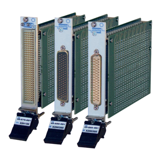
- Page 1 40-575/576/577/578/579 User Manual PXI 2 Amp 1-Pole Ultra High Density Matrix Modules pickeringtest.com Issue 5.3 March 2022...
- Page 2 © COPYRIGHT (2022) PICKERING INTERFACES. ALL RIGHTS RESERVED. No part of this publication may be reproduced, transmitted, transcribed, translated or stored in any form, or by any means without the written permission of Pickering Interfaces. Technical details contained within this publication are subject to change without notice.
- Page 3 Pickering Interfaces strives to fulfil all relevant environmental laws and regulations and reduce wastes and releases to the environment. Pickering Interfaces aims to design and operate products in a way that protects the environment and the health and safety of its employees, customers and the public. Pickering Interfaces endeavours to develop and manufacture products that can be produced, distributed, used and recycled, or disposed of, in a safe and environmentally friendly manner.
-
Page 4: Product Safety
If this product is heavy reference should be made to the safety instructions for provisions of lifting and moving. STATIC SENSITIVE To indicate that static sensitive devices are present and handling precautions should be followed. REED RELAY MODULE 40-110/115/120/125 2 AMP 1-POLE UHD MATRIX MODULES 40-575/576/577/578/579 Page (IV) Page (IV) -
Page 5: Table Of Contents
Using IVI Driver, Direct I/O Driver or VISA Driver ....4.3 Section 5 Connector Information ..............5.1 Section 6 Trouble Shooting .................6.1 Section 7 Maintenance Information ............7.1 Switching System Test Tools ..........7.1 Relay Fault Finding ...............7.2 2 AMP 1-POLE UHD MATRIX MODULES 40-575/576/577/578/579 Page (V) - Page 6 THIS PAGE INTENTIONALLY BLANK 2 AMP 1-POLE UHD MATRIX MODULES 40-575/576/577/578/579 Page (VI)
-
Page 7: Warnings And Cautions
Not to be used in safety critical circuits, refer to the Pickering Interfaces’ terms & conditions of sale. This module must not be used for the switching of Mains Circuits. For the switching of voltages up to the module’s full specification, Secondary Circuit power supplies and the Device Under Test must... - Page 8 • For suitably equipped products in the event of an emergency press the red “emergency stop” button situated on the front of the unit. 2 AMP 1-POLE UHD MATRIX MODULES 40-575/576/577/578/579 Page (VIII) 2 AMP 1-POLE UHD MATRIX MODULES 40-575 / 576 / 577 / 578 / 579 Page (VIII)
-
Page 9: Technical Specification
40-575-001 84x4 Matrix Switching Diagram The 40-575 supports 4 concurrent switch paths for X to X and Y to X connections, however connections between different Y axis lines (e.g. Y1 to Y2, Y3 or Y4) are not permitted by the driver. - Page 10 Matrix Functionality The 40-579 permits 14 concurrent X to X paths or 16 ✔ concurrent Y to X paths, the 40-575, 40-576, 40-577 ✔ and 40-578 permit 4, 6, 8 and 12 concurrent X to X or X to Y paths respectively. As shown in the figure below, X to Y connections (e.g.
- Page 11 SECTION 1 - TECHNICAL SPECIFICATION pickering Specifications 2 Amp 1-Pole UHD Matrix – 40-575/6/7/8/9 Relay Type RF Specification The 40-575 Series modules are fitted with electro-mechanical 40-575 10MHz relays (Palladium-Ruthenium, Gold Covered Bifurcated). 40-576 10MHz Bandwidth Switching Specification (-3dB) 40-577...
- Page 12 93-002-001 93-002-410 Product Customization 40-576/577 93-006-001 Not Required Pickering PXI modules are designed and manufactured on our own 40-578/579 93-005-001 Not Required flexible manufacturing lines, giving complete product control and Spare Relay Kits enabling simple customization to meet very specific requirements.
- Page 13 We provide a full range of supporting cable and connector solutions for all our switching products—20 connector families with 1200+ products. We offer everything from simple mating connectors to complex cables assemblies and terminal blocks. All assemblies are manufactured by Pickering and are guaranteed to mechanically and electrically mate to our modules. Connectors & Backshells...
- Page 14 2 Amp 1-Pole UHD Matrix – 40-575/6/7/8/9 Programming Pickering provide kernel, IVI and VISA (NI & Keysight) drivers which are compatible with all Microsoft supported versions of Windows and popular older versions. For a list of all supporting operating systems, please see: pickeringtest.com/os...
-
Page 15: Technical Description
The module comprises a mother board and a daughter board populated with 1-pole electro-mechanical relays configured as an 84x4 (40-575), a 64x6 (40-576), a 50x8 (40-577), a 36x12 (40-578) or a 28x16 (40-579) matrix. The relays are energised via control signals from relay drivers U5 to U20. Each relay driver is loaded with serial data from PCI bridge U1 to operate the required matrix crosspoint.The main PCI interface circuitry and the drivers and... - Page 16 SECTION 2 - TECHNICAL DESCRIPTION pickering THIS PAGE INTENTIONALLY BLANK 2 AMP 1-POLE UHD MATRIX MODULES 40-575/576/577/578/579 Page 2.2...
-
Page 17: Installation
Modular products require installation in a suitable PXI/LXI chassis. The module is designed for indoor use only. PREOPERATION CHECKS (UNPACKING) 1. Check the module for transport damage and report any damage immediately to Pickering Interfaces. Do not attempt to install the product if any damage is evident. -
Page 18: Hardware Installation
For a system comprising more than one chassis, turn ON the last chassis in the system followed by the penultimate, etc, and finally turn ON the external controller or chassis containing the system controller. 9. For Pickering Interfaces modular LXI installation there is no requirement to use any particular power up sequence. -
Page 19: Testing Operation
Figure 3.2 - General Soft Front Panel Icon A selector panel will appear, listing all installed Pickering PCI, PXI or LXI switch cards and resistor cards. Click on the card you wish to control, and a graphical control panel is presented allowing operation of the card. - Page 20 SECTION 3 - INSTALLATION pickering THIS PAGE INTENTIONALLY BLANK 2 AMP 1-POLE UHD MATRIX MODULES 40-575/576/577/578/579 Page 3.4...
-
Page 21: Programming Guide
SECTION 4 - PROGRAMMING PROGRAMMING OPTIONS FOR PICKERING INTERFACES PXI MODULES For information on the installation and use of drivers and the programming of Pickering’s products in various software environments, please refer to the Software User Manual. This is available as a download from: https://www.pickeringtest.com/support/software-drivers-and-downloads... -
Page 22: Programming The Uhd Matrix
PROGRAMMING THE UHD MATRIX The 40-575 is a single pole switching matrix with 84 connections on the X-axis and 4 connections on the Y-axis. Connections are made by operating the relays at the crosspoints between X and Y lines allowing single X-Y connections, or X-X connections using a Y line as a path. -
Page 23: Using Ivi Driver, Direct I/O Driver Or Visa Driver
Once the drivers are installed the manual “Sys40Prg.pdf” and driver help files which fully describes these functions can be found in the Pickering folder(s) or the Pickering entries on your Start Menu. The card must be opened before use and closed after using the following function calls: Direct Driver - Open with PIL_OpenCards or PIL_OpenSpecifiedCard and close with PIL_CloseCards or PIL_CloseSpecifiedCards respectively. - Page 24 SECTION 4 - PROGRAMMING GUIDE pickering THIS PAGE INTENTIONALLY BLANK 2 AMP 1-POLE UHD MATRIX MODULES 40-575/576/577/578/579 Page 4.4...
- Page 25 SECTION 5 - CONNECTOR INFORMATION pickering SECTION 5 - CONNECTOR INFORMATION Figure 5.1 - 2 Amp 1-Pole 84x4 Matrix Module 40-575-001: 160-pin DIN41612 male connector pinout viewed from front of module. 2 AMP 1-POLE UHD MATRIX MODULES 40-575/576/577/578/579 Page 5.1...
- Page 26 SECTION 5 - CONNECTOR INFORMATION pickering FP-GND Figure 5.2 - 2 Amp 1-Pole 64x6 Matrix Module 40-576-001: 78-pin D-type male connector pinout viewed from front of module. 2 AMP 1-POLE UHD MATRIX MODULES 40-575/576/577/578/579 Page 5.2...
- Page 27 SECTION 5 - CONNECTOR INFORMATION pickering FP-GND Figure 5.3 - 2 Amp 1-Pole 50x8 Matrix Module 40-577-001: 78-pin D-type male connector pinout viewed from front of module. 2 AMP 1-POLE UHD MATRIX MODULES 40-575/576/577/578/579 Page 5.3...
- Page 28 SECTION 5 - CONNECTOR INFORMATION pickering FP-GND Figure 5.4 - 2 Amp 1-Pole 36x12 Matrix Module 40-578-001: 50-pin D-type male connector pinout viewed from front of module. 2 AMP 1-POLE UHD MATRIX MODULES 40-575/576/577/578/579 Page 5.4...
- Page 29 SECTION 5 - CONNECTOR INFORMATION pickering FP-GND Figure 5.5 - 2 Amp 1-Pole 28x16 Matrix Module 40-579-001: 50-pin D-type male connector pinout viewed from front of module. 2 AMP 1-POLE UHD MATRIX MODULES 40-575/576/577/578/579 Page 5.5...
- Page 30 SECTION 5 - CONNECTOR INFORMATION pickering THIS PAGE INTENTIONALLY BLANK 2 AMP 1-POLE UHD MATRIX MODULES 40-575/576/577/578/579 Page 5.6...
-
Page 31: Trouble Shooting
PCI configuration, highlighting any potential configuration problems. Specific details of all installed Pickering switch cards are included. All the installed Pickering switch cards should be listed in the “Pilpxi information” section - if one or more cards is missing it may be possible to determine the reason by referring to the PCI configuration dump contained in the report, but interpretation of this information is far from straightforward, and the best course is to contact Pickering support: support@pickeringtest.com, if possible... - Page 32 SECTION 6 - TROUBLE SHOOTING pickering THIS PAGE INTENTIONALLY BLANK 2 AMP 1-POLE UHD MATRIX MODULES 40-575/576/577/578/579 Page 6.2...
-
Page 33: Maintenance Information
For PXI modules which are supported in one of Pickering Interfaces’ Modular LXI Chassis (such as the 60-102B and 60-103B) no module software update is required. If the module was introduced after the LXI chassis was manufactured the module may not be recognized, in this case the chassis firmware may need upgrading. -
Page 34: Relay Fault Finding
RELAY FAULT FINDING In the event of a switch failure in a module in the 40-575 range the following procedure will help locate which relays need replacing. The module uses through-hole relays that are straight forward to replace providing normal good practice is followed to avoid PCB damage. - Page 35 SECTION 7 - MAINTENANCE INFORMATION pickering RELAYS USED IN SIGNAL PATH - 40-575 (84x4 MATRIX) 128 127 128 127 129 127 129 127 131 130 131 130 132 130 132 130 134 133 134 133 135 133 135 133 137 136...
- Page 36 RL84 RL100 RL101 RL102 RL123 RL122 RL121 RL97 RL98 RL99 RL115 RL116 RL117 Figure 7.2 - 40-575 Matrix Module: Motherboard Relay Locations Figure 7.3 - 40-575 Matrix Module: Daughterboard Relay Locations 2 AMP 1-POLE UHD MATRIX MODULES 40-575/576/577/578/579 Page 7.4...
- Page 37 SECTION 7 - MAINTENANCE INFORMATION pickering RELAYS USED IN SIGNAL PATH - 40-576 (64x6 MATRIX) 2 AMP 1-POLE UHD MATRIX MODULES 40-575/576/577/578/579 Page 7.5...
- Page 38 RL99 RL100 RL125 RL126 RL127 RL128 RL111 RL113 RL114 RL115 RL116 RL117 RL118 RL119 RL120 RL112 Spare Figure 7.4 - 40-576 Matrix Module: Motherboard Relay Locations Figure 7.5 - 40-576 Matrix Module: Daughterboard Relay Locations 2 AMP 1-POLE UHD MATRIX MODULES 40-575/576/577/578/579 Page 7.6...
- Page 39 SECTION 7 - MAINTENANCE INFORMATION pickering RELAYS USED IN SIGNAL PATH - 40-577 (50x8 MATRIX) 2 AMP 1-POLE UHD MATRIX MODULES 40-575/576/577/578/579 Page 7.7...
- Page 40 RL99 RL100 RL111 RL112 RL109 RL110 RL116 RL117 RL118 RL119 RL120 RL113 RL114 RL115 Spare Figure 7.6 - 40-577 Matrix Module: Motherboard Relay Locations Figure 7.7 - 40-577 Matrix Module: Daughterboard Relay Locations 2 AMP 1-POLE UHD MATRIX MODULES 40-575/576/577/578/579 Page 7.8...
- Page 41 SECTION 7 - MAINTENANCE INFORMATION pickering RELAYS USED IN SIGNAL PATH - 40-578 (36x12 MATRIX) 2 AMP 1-POLE UHD MATRIX MODULES 40-575/576/577/578/579 Page 7.9...
- Page 42 RL97 RL98 RL68 RL69 RL99 RL100 RL101 RL102 RL103 RL104 RL105 RL70 Spare Figure 7.8 - 40-578 Matrix Module: Motherboard Relay Locations Figure 7.9 - 40-578 Matrix Module: Daughterboard Relay Locations 2 AMP 1-POLE UHD MATRIX MODULES 40-575/576/577/578/579 Page 7.10...
- Page 43 SECTION 7 - MAINTENANCE INFORMATION pickering RELAYS USED IN SIGNAL PATH - 40-579 (28x16 MATRIX) 2 AMP 1-POLE UHD MATRIX MODULES 40-575/576/577/578/579 Page 7.11...
- Page 44 RL118 RL126 RL125 RL124 RL123 RL122 RL121 RL120 RL119 RL109 RL117 RL116 RL115 RL114 RL113 RL112 RL111 RL110 Spare Figure 7.10 - 40-579 Matrix Module: Motherboard Relay Locations Figure 7.11 - 40-579 Matrix Module: Daughterboard Relay Locations 2 AMP 1-POLE UHD MATRIX MODULES 40-575/576/577/578/579 Page 7.12...
Need help?
Do you have a question about the 40-575 and is the answer not in the manual?
Questions and answers