
Related Manuals for Pickering 40-540


Summary of Contents for Pickering 40-540
- Page 1 40-540/541/542 User Manual PXI Ultra High Density Matrix Modules pickeringtest.com Issue 5.6 May 2023...
- Page 2 © COPYRIGHT (2023) PICKERING INTERFACES. ALL RIGHTS RESERVED. No part of this publication may be reproduced, transmitted, transcribed, translated or stored in any form, or by any means without the written permission of Pickering Interfaces. Technical details contained within this publication are subject to change without notice.
- Page 3 Pickering Interfaces strives to fulfil all relevant environmental laws and regulations and reduce wastes and releases to the environment. Pickering Interfaces aims to design and operate products in a way that protects the environment and the health and safety of its employees, customers and the public. Pickering Interfaces endeavours to develop and manufacture products that can be produced, distributed, used and recycled, or disposed of, in a safe and environmentally friendly manner.
-
Page 4: Product Safety
If this product is heavy reference should be made to the safety instructions for provisions of lifting and moving. STATIC SENSITIVE To indicate that static sensitive devices are present and handling precautions should be followed. REED RELAY MODULE 40-110/115/120/125 ULTRA HIGH DENSITY MATRIX MODULES 40-540/541/542 Page (IV) Page (IV) -
Page 5: Table Of Contents
Pre Operation Checks ............3.1 Hardware Installation ............3.2 Software Installation .............3.2 Testing Operation ..............3.3 Section 4 Programming Guide ..............4.1 Programming Options For Pickering PXI Modules ....4.1 Module Architecture ..............4.2 Programming The Module ............4.3 Section 5 Connector Information ..............5.1 Section 6 Trouble Shooting .................6.1 Section 7 Maintenance Information ............7.1... - Page 6 THIS PAGE INTENTIONALLY BLANK ULTRA HIGH DENSITY MATRIX MODULES 40-540/541/542 Page (VI)
-
Page 7: Warnings And Cautions
Not to be used in safety critical circuits, refer to the Pickering Interfaces’ terms & conditions of sale. This module must not be used for the switching of Mains Circuits. For the switching of voltages up to the module’s full specification, Secondary Circuit power supplies and the Device Under Test must... - Page 8 • For suitably equipped products in the event of an emergency press the red “emergency stop” button situated on the front of the unit. 2 AMP 1-POLE UHD MATRIX MODULES 40-575 / 576 / 577 / 578 / 579 ULTRA HIGH DENSITY MATRIX MODULES 40-540/541/542 Page (VIII) Page (VIII)
-
Page 9: Technical Specification
Supported by eBIRST ™ y 3 Year Warranty The world’s highest density single slot PXI reed relay matrix module, the 40-540/541/542, is available as a 132x4, 66x8 or 33x16 matrix with 1-pole switching. Supported by eBIRST Typical applications include signal routing in functional ATE and data acquisition systems. - Page 10 1 2 3 4 1 2 3 4 1 2 3 4 The 40-540, 40-541 and 40-542 may be ordered partially populated to a specific matrix configuration (if volumes dictate), the diagrams show some example configurations. The illustrations right show: •...
- Page 11 1000, dependant upon load type (ranging from >10 operations for low power loads to >1x10 operations for high power loads). pickeringtest.com ULTRA HIGH DENSITY MATRIX MODULES 40-540/541/542 Page 1.3...
- Page 12 Specifications Ultra High Density Matrix, 40-540/541/542 Relay Type The 40-540/541/542 modules are fitted with ruthenium sputtered reed relays, these offer very long life with good low level switching performance and excellent contact resistance stability. Spare reed relays are built onto the circuit board to allow easy maintenance with minimum downtime.
- Page 13 PICKERING INTERFACES BRIC™ MATRIX MODULES For applications that require a very large number of matrix crosspoints, Pickering’s range of versatile BRIC modules should be considered. The BRIC4 is a 4-slot PXI module available with over 2200 crosspoints, the BRIC8 is an 8-slot PXI module available with over 4400 crosspoints.
- Page 14 93-006-222 93-015-103 Product Customization Spare Relay Kits Pickering modules are designed and manufactured on our Kits of replacement relays are available for the majority of own flexible manufacturing lines, giving complete product Pickering’s PXI switching products, simplifying servicing control and enabling simple customization to meet very and reducing down-time.
- Page 15 We provide a full range of supporting cable and connector solutions for all our switching products—20 connector families with 1200+ products. We offer everything from simple mating connectors to complex cables assemblies and terminal blocks. All assemblies are manufactured by Pickering and are guaranteed to mechanically and electrically mate to our modules. Connectors & Backshells...
- Page 16 Ultra High Density Matrix, 40-540/541/542 Programming Pickering provide kernel, IVI and VISA (NI & Keysight) drivers which are compatible with all Microsoft supported versions of Windows and popular older versions. For a list of all supporting operating systems, please see: pickeringtest.com/os...
-
Page 17: Functional Description
The module comprises a mother board and a daughter board populated with single pole ruthenium reed relays configured as a 132x4 (40-540), a 66x8 (40-541) or a 33x16 (40-542) matrix. The relays are energised via control signals from relay drivers U50 to U82. Each relay driver is loaded with serial data from PCI bridge U1 to operate the required matrix crosspoint.The main PCI interface circuitry and the drivers and relays that make up one half of the... - Page 18 SECTION 2 - TECHNICAL DESCRIPTION pickering THIS PAGE INTENTIONALLY BLANK ULTRA HIGH DENSITY MATRIX MODULES 40-540/541/542 Page 2.2...
-
Page 19: Installation
Modular products require installation in a suitable PXI/LXI chassis. The module is designed for indoor use only. PREOPERATION CHECKS (UNPACKING) 1. Check the module for transport damage and report any damage immediately to Pickering Interfaces. Do not attempt to install the product if any damage is evident. -
Page 20: Hardware Installation
For a system comprising more than one chassis, turn ON the last chassis in the system followed by the penultimate, etc, and finally turn ON the external controller or chassis containing the system controller. 9. For Pickering Interfaces modular LXI installation there is no requirement to use any particular power up sequence. -
Page 21: Testing Operation
Figure 3.2 - General Soft Front Panel Icon A selector panel will appear, listing all installed Pickering PCI, PXI or LXI switch cards and resistor cards. Click on the card you wish to control, and a graphical control panel is presented allowing operation of the card. - Page 22 SECTION 3 - INSTALLATION pickering THIS PAGE INTENTIONALLY BLANK ULTRA HIGH DENSITY MATRIX MODULES 40-540/541/542 Page 3.4...
-
Page 23: Programming Guide
SECTION 4 - PROGRAMMING GUIDE PROGRAMMING OPTIONS FOR PICKERING INTERFACES PXI MODULES For information on the installation and use of drivers and the programming of Pickering’s products in various software environments, please refer to the Software User Manual. This is available as a download from: https://www.pickeringtest.com/support/software-drivers-and-downloads... -
Page 24: Module Architecture
MODULE ARCHITECTURE The 40-540 is a single pole switching matrix with 132 connections on the X-axis and 4 connections on the Y-axis. Connections are made by operating the relays at the crosspoints between X and Y lines allowing single X-Y connections, or X-X connections using a Y line as a path. -
Page 25: Programming The Module
Once the drivers are installed the manual “Sys40Prg.pdf” and driver help files which fully describes these functions can be found in the Pickering folder(s) or the Pickering entries on your Start Menu. The card must be opened before use and closed after using the following function calls: Direct I/O Driver - Open with PIL_OpenCards or PIL_OpenSpecifiedCard and close with PIL_CloseCards or PIL_CloseSpecifiedCards respectively. - Page 26 SECTION 4 - PROGRAMMING GUIDE pickering THIS PAGE INTENTIONALLY BLANK ULTRA HIGH DENSITY MATRIX MODULES 40-540/541/542 Page 4.4...
-
Page 27: Connector Information
X123 X124 X125 X126 X127 X128 X129 X130 X131 X132 SGND Figure 5.1 - Pin Outs: 132x4 Ultra High Density Matrix Module 40-540 (200-pin Female LFH connector viewed from front of module) ULTRA HIGH DENSITY MATRIX MODULES 40-540/541/542 Page 5.1... - Page 28 Figure 5.3 - Pin Outs: 33x16 Ultra High Density Matrix Module 40-541 Density Matrix Module 40-542 (96-pin Male micro-D connector (68-pin Male micro-D connector viewed from front of module) viewed from front of module) ULTRA HIGH DENSITY MATRIX MODULES 40-540/541/542 Page 5.2...
-
Page 29: Trouble Shooting
PCI configuration, highlighting any potential configuration problems. Specific details of all installed Pickering switch cards are included. All the installed Pickering switch cards should be listed in the “Pilpxi information” section - if one or more cards is missing it may be possible to determine the reason by referring to the PCI configuration dump contained in the report, but interpretation of this information is far from straightforward, and the best course is to contact Pickering support: support@pickeringtest.com, if possible... - Page 30 SECTION 6 - TROUBLE SHOOTING pickering THIS PAGE INTENTIONALLY BLANK ULTRA HIGH DENSITY MATRIX MODULES 40-540/541/542 Page 6.2...
-
Page 31: Maintenance Information
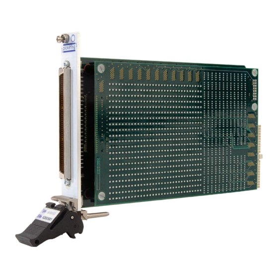
For PXI modules which are supported in one of Pickering Interfaces’ Modular LXI Chassis (such as the 60-102B and 60-103B) no module software update is required. If the module was introduced after the LXI chassis was manufactured the module may not be recognized, in this case the chassis firmware may need upgrading. - Page 32 SECTION 7 - MAINTENANCE INFORMATION pickering Figure 7.1 - 40-540/541/542 Ultra High Density Matrix Module ULTRA HIGH DENSITY MATRIX MODULES 40-540/541/542 Page 7.2...
- Page 33 SECTION 7 - MAINTENANCE INFORMATION pickering RELAY LOOK-UP TABLES - 40-540 Relays highlighted in blue are on the motherboard and relays highlighted in yellow are on the daughterboard. 40-540 132x4 MATRIX RELAY CROSS REFERENCE Cross- Cross- Cross- Cross- Cross- Cross-...
- Page 34 SECTION 7 - MAINTENANCE INFORMATION pickering 40-540 132x4 MATRIX RELAY CROSS REFERENCE Cross- Cross- Cross- Cross- Cross- Cross- Relay Relay Relay Relay Relay Relay point point point point point point RL179 RL355 RL180 RL356 RL183 RL359 RL184 RL360 RL11 RL187...
- Page 35 SECTION 7 - MAINTENANCE INFORMATION pickering Figure 7.2 - 40-540 Motherboard Component Layout ULTRA HIGH DENSITY MATRIX MODULES 40-540/541/542 Page 7.5...
- Page 36 RL520 RL457 RL458 RL459 RL460 RL461 RL462 RL463 RL464 RL521 RL522 RL523 RL524 RL465 RL466 RL467 RL468 RL469 RL470 RL471 RL472 RL525 RL526 RL527 RL528 Figure 7.3 - 40-540 Daughterboard Component Layout ULTRA HIGH DENSITY MATRIX MODULES 40-540/541/542 Page 7.6...
- Page 37 RL132 RL484 RL313 RL138 RL490 RL315 RL140 RL492 RL321 RL146 RL498 RL323 RL148 RL500 RL329 RL154 RL506 RL331 RL156 RL508 RL337 RL162 RL514 RL339 RL164 RL516 RL345 RL170 RL522 RL347 RL172 RL524 ULTRA HIGH DENSITY MATRIX MODULES 40-540/541/542 Page 7.7...
- Page 38 RL136 RL488 RL317 RL142 RL494 RL319 RL144 RL496 RL325 RL150 RL502 RL327 RL152 RL504 RL333 RL158 RL510 RL335 RL160 RL512 RL341 RL166 RL518 RL343 RL168 RL520 RL349 RL174 RL526 RL351 RL176 RL528 ULTRA HIGH DENSITY MATRIX MODULES 40-540/541/542 Page 7.8...
- Page 39 SECTION 7 - MAINTENANCE INFORMATION pickering Figure 7.4 - 40-541 Motherboard Component Layout ULTRA HIGH DENSITY MATRIX MODULES 40-540/541/542 Page 7.9...
- Page 40 RL520 RL457 RL458 RL459 RL460 RL461 RL462 RL463 RL464 RL521 RL522 RL523 RL524 RL465 RL466 RL467 RL468 RL469 RL470 RL471 RL472 RL525 RL526 RL527 RL528 Figure 7.5 - 40-541 Daughterboard Component Layout ULTRA HIGH DENSITY MATRIX MODULES 40-540/541/542 Page 7.10...
- Page 41 RL323 RL355 RL19 RL240 RL272 RL67 RL324 RL356 RL20 RL241 RL273 RL68 RL325 RL357 RL21 RL242 RL274 RL69 RL326 RL358 RL22 RL243 RL275 RL70 RL327 RL359 RL23 RL244 RL276 RL71 RL328 RL360 ULTRA HIGH DENSITY MATRIX MODULES 40-540/541/542 Page 7.11...
- Page 42 RL491 RL523 RL115 RL408 RL440 RL163 RL492 RL524 RL116 RL409 RL441 RL164 RL493 RL525 RL117 RL410 RL442 RL165 RL494 RL526 RL118 RL411 RL443 RL166 RL495 RL527 RL119 RL412 RL444 RL167 RL496 RL528 ULTRA HIGH DENSITY MATRIX MODULES 40-540/541/542 Page 7.12...
- Page 43 SECTION 7 - MAINTENANCE INFORMATION pickering Figure 7.6 - 40-542 Motherboard Component Layout ULTRA HIGH DENSITY MATRIX MODULES 40-540/541/542 Page 7.13...
- Page 44 RL381 RL465 RL469 RL471 RL473 RL475 RL488 RL490 RL492 RL494 RL496 RL462 RL400 RL484 RL401 RL485 RL402 RL486 RL509 RL511 RL513 RL515 RL517 RL507 RL528 Figure 7.7 - 40-542 Daughterboard Component Layout ULTRA HIGH DENSITY MATRIX MODULES 40-540/541/542 Page 7.14...
Need help?
Do you have a question about the 40-540 and is the answer not in the manual?
Questions and answers