
Related Manuals for Pickering 40-565A


Summary of Contents for Pickering 40-565A
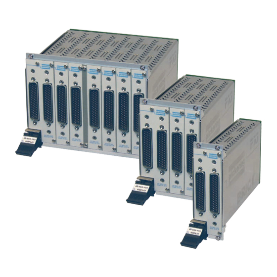
- Page 1 40-565A User Manual PXI 2 A BRIC™ Multi-Slot Matrix Modules pickeringtest.com Issue 5.9 March 2021...
- Page 2 © COPYRIGHT (2021) PICKERING INTERFACES. ALL RIGHTS RESERVED. No part of this publication may be reproduced, transmitted, transcribed, translated or stored in any form, or by any means without the written permission of Pickering Interfaces. Technical details contained within this publication are subject to change without notice.
- Page 3 Pickering Interfaces strives to fulfil all relevant environmental laws and regulations and reduce wastes and releases to the environment. Pickering Interfaces aims to design and operate products in a way that protects the environment and the health and safety of its employees, customers and the public. Pickering Interfaces endeavours to develop and manufacture products that can be produced, distributed, used and recycled, or disposed of, in a safe and environmentally friendly manner.
-
Page 4: Product Safety
If this product is heavy reference should be made to the safety instructions for provisions of lifting and moving. STATIC SENSITIVE To indicate that static sensitive devices are present and handling precautions should be followed. REED RELAY MODULE 40-110/115/120/125 BRIC INTEGRATED PXI 2-AMP MATRIX WITH BIRST™ (40-565A) Page (IV) Page (IV) -
Page 5: Table Of Contents
Using Built-In Relay Self Test (BIRST) ......... 6.2 Section 7 Maintenance Information ............7.1 Fuse Replacement ..............7.1 Relay Look-Up Tables ............7.2 PCB Layout Diagrams ............7.11 Card Removal From BRIC............. 7.13 Card Replacement ..............7.15 BRIC INTEGRATED PXI 2-AMP MATRIX WITH BIRST™ (40-565A) Page (V) - Page 6 THIS PAGE INTENTIONALLY BLANK BRIC INTEGRATED PXI 2-AMP MATRIX WITH BIRST™ (40-565A) Page (VI)
-
Page 7: Warnings And Cautions
Not to be used in safety critical circuits, refer to the Pickering Interfaces’ terms & conditions of sale. This module must not be used for the switching of Mains Circuits. For the switching of voltages up to the module’s full specification, Secondary Circuit power supplies and the Device Under Test must... - Page 8 • For suitably equipped products in the event of an emergency press the red “emergency stop” button situated on the front of the unit. 2 AMP 1-POLE UHD MATRIX MODULES 40-575 / 576 / 577 / 578 / 579 BRIC INTEGRATED PXI 2-AMP MATRIX WITH BIRST™ (40-565A) Page (VIII) Page (VIII)
-
Page 9: Technical Specification
High Reliability and Easy of Use BRIC™ 2nd Generation PXI 2 A Switch Matrix The 40-565A PXI BRIC is designed to minimise the cost The 40-565A BRIC is a range of high density matrix and complexity of cable assemblies to the device under modules able to switch up to 2 A at 150 VDC/100 VAC. - Page 10 The 40-565A in BRIC4 Format is Available With Matrix Configurations Between 24x8 and 96x8 (2-Pole) X192 The 40-565A in BRIC8 Format is Available With Matrix Configurations Between 44x8 and 352x8 (2-Pole) pickeringtest.com BRIC INTEGRATED PXI 2-AMP MATRIX WITH BIRST™ (40-565A) Page 1.2...
- Page 11 Overview pickering 2 A BRIC Multi-Slot Matrix, 40-565A Example Configurations of the 40-565A 2 Amp BRIC Matrix Schematic diagram showing a 192x8 BRIC Matrix being used to parallel test multiple DUTs. The BRIC Matrix allows tremendous test system flexibility. Performance & Cost Comparison With Competing Platforms for a Typical 192x8 Matrix (2-pole switching)
- Page 12 Discovering the source of the problem takes time and effort users may not have when working to tight schedules. To ensure low cost of ownership, Pickering Interfaces has now incorporated a test tool, BIRST, into the BRIC. BIRST This is a sophisticated diagnostic tool, which allows a complete relay self test of a BRIC module.
- Page 13 PCB when the change is made, especially if the relays are surface mount devices. Pickering has greatly improved the test methodology to the extent it is now possible to include full self test in PXI switch modules with minimal impact on cost and switching density, welcome news for users who are used to having such features in their solutions.
- Page 14 2 A BRIC Multi-Slot Matrix, 40-565A Relay Type Width and Dimensions The 40-565A BRIC modules are fitted with electro- Two, four or eight slot 3U PXI module (CompactPCI). mechanical relays. 3D models for these modules in a variety of popular file General Switching Specification formats are available on request.
- Page 15 BRIC8 - 8-Slot High Density Matrix Mating Connectors & Cabling 2 A 2-Pole 24x8 Matrix 40-565A-102-24x8 For connection accessories for the 40-565A module please 2 A 2-Pole 48x8 Matrix 40-565A-102-48x8 refer to the 90-006D 78-pin D-type Connector Accessories...
- Page 16 We provide a full range of supporting cable and connector solutions for all our switching products—20 connector families with 1200+ products. We offer everything from simple mating connectors to complex cables assemblies and terminal blocks. All assemblies are manufactured by Pickering and are guaranteed to mechanically and electrically mate to our modules. Connectors & Backshells...
- Page 17 2 A BRIC Multi-Slot Matrix, 40-565A Programming Pickering provide kernel, IVI and VISA (NI & Keysight) drivers which are compatible with all Microsoft supported versions of Windows and popular older versions. For a list of all supporting operating systems, please see: pickeringtest.com/os...
- Page 18 SECTION 1 - TECHNICAL SPECIFICATION pickering THIS PAGE INTENTIONALLY BLANK BRIC INTEGRATED PXI 2-AMP MATRIX WITH BIRST™ (40-565A) Page 1.10...
-
Page 19: Technical Description
The backplane provides mounting for the 36-pin connectors (into which the Sub-Matrix Cards plug) and Control logic. Figure 2.1 - Fully Populated 40-565A BRIC8 Matrix Module FUNCTIONAL DESCRIPTION A functional block diagram is provided in Figure 2.3. The BRIC Module is powered by a +5V input via Compact PCI connector J1 mounted on the Backplane. - Page 20 Front Panel 78-pin D-type Connector Isolation MATRIX CARD 2 Switches Front Panel 78-pin D-type Connector X169 X192 Isolation MATRIX CARD 8 Switches Figure 2.2 - 40-565A BRIC Module: Switching Architecture BRIC INTEGRATED PXI 2-AMP MATRIX WITH BIRST™ (40-565A) Page 2.2...
- Page 21 2-Slot Backplane. COILS RELAY 8 Mother/Daughter board assemblies DRIVERS U11 TO U20 X BUS are fitted to the 8-Slot Backplane. DAUGHTER BOARD Figure 2.3 - 40-565A BRIC Module: Functional Block Diagram BRIC INTEGRATED PXI 2-AMP MATRIX WITH BIRST™ (40-565A) Page 2.3...
- Page 22 SECTION 2 - TECHNICAL DESCRIPTION pickering THIS PAGE INTENTIONALLY BLANK BRIC INTEGRATED PXI 2-AMP MATRIX WITH BIRST™ (40-565A) Page 2.4...
-
Page 23: Installation
Modular products require installation in a suitable PXI/LXI chassis. The module is designed for indoor use only. PREOPERATION CHECKS (UNPACKING) 1. Check the module for transport damage and report any damage immediately to Pickering Interfaces. Do not attempt to install the product if any damage is evident. -
Page 24: Hardware Installation
For a system comprising more than one chassis, turn ON the last chassis in the system followed by the penultimate, etc, and finally turn ON the external controller or chassis containing the system controller. 9. For Pickering Interfaces modular LXI installation there is no requirement to use any particular power up sequence. -
Page 25: Testing Operation
Figure 3.2 - General Soft Front Panel Icon A selector panel will appear, listing all installed Pickering PCI, PXI or LXI switch cards and resistor cards. Click on the card you wish to control, and a graphical control panel is presented allowing operation of the card. - Page 26 SECTION 3 - INSTALLATION pickering THIS PAGE INTENTIONALLY BLANK BRIC INTEGRATED PXI 2-AMP MATRIX WITH BIRST™ (40-565A) Page 3.4...
-
Page 27: Programming Guide
SECTION 4 - PROGRAMMING PROGRAMMING OPTIONS FOR PICKERING INTERFACES PXI MODULES For information on the installation and use of drivers and the programming of Pickering’s products in various software environments, please refer to the Software User Manual. This is available as a download from: https://www.pickeringtest.com/support/software-drivers-and-downloads... -
Page 28: Module Architecture
The 40-565A is a high density 2-pole switching matrix constructed from 24x8 sub-matrix cards linked with an analog backplane. The 40-565A module can be fitted with 1 or 2 sub-matrix cards (BRIC2), between 1 & 4 sub-matrix cards (BRIC4) or between 1 & 8 sub-matrix cards (BRIC8). Connections are made by operating the crosspoint relays between X and Y lines allowing single X-Y connections, or X-X connections using a Y line as a path - all signal paths are 2-pole. -
Page 29: Programming The Module - Standard Version
Using The IVI Driver, Direct I/O Driver or VISA Driver This section provides some code fragments which show how to control the standard versions of the 40-565A BRIC Matrix using the IVI Driver, Direct I/O Driver or the VISA Driver. -
Page 30: Programming The Module - Independent Isolation
PROGRAMMING THE MODULE - INDEPENDENT ISOLATION VERSION Independent isolation versions of the 40-565A are identified by an “ii” suffix (e.g. 40-565A-102-192x8-ii). For all configurations of this version, the entire matrix is treated as a single programming sub-unit designated as Sub-Unit 1, and the isolation switches of all sub-matrix cards are contained in a single sub-unit designated as Sub-Unit 2. - Page 31 Bit 61 Bit 62 Bit 63 Bit 64 SUB-MATRIX CARD 8 Figure 4.2 - 40-565A Matrix Module (Independent Isolation Version) - Sub-unit Allocations Note: All signal paths shown are 2-wire connections BRIC INTEGRATED PXI 2-AMP MATRIX WITH BIRST™ (40-565A) Page 4.5...
- Page 32 Using the IVI Driver The IVI driver assigns names to each channel or node. To program the 40-565A BRIC matrix from the IVI driver it is necessary to know the name of these channels. The channel naming for the matrix is shown in Table 4.2 and the channel naming for the isolation switches is shown in Table 4.3.
- Page 33 “Y6” Connects Y7 Connects Y7 comB31, chB31 comB63, chB63 to backplane “Y7” to backplane “Y7” Connects Y8 Connects Y8 comB32, chB32 comB64, chB64 to backplane “Y8” to backplane “Y8” BRIC INTEGRATED PXI 2-AMP MATRIX WITH BIRST™ (40-565A) Page 4.7...
- Page 34 SECTION 4 - PROGRAMMING GUIDE pickering THIS PAGE INTENTIONALLY BLANK BRIC INTEGRATED PXI 2-AMP MATRIX WITH BIRST™ (40-565A) Page 4.8...
-
Page 35: Connector Information
SECTION 5 - CONNECTOR INFORMATION Figures 5.1 shows the connector positioning for the 40-565A Matrix Module. Figures 5.2 to 5.9 provide the pinouts for the 78-pin D-type connectors on the individual matrix cards. In its minimum configuration, the matrix has a single matrix card in position 1. - Page 36 Y7.1 Y8.1 Y8.2 Y7.2 FP_GND FP_GND Figure 5.2 - 40-565A Matrix Card 1 Pinout Figure 5.3 - 40-565A Matrix Card 2 Pinout 78-pin Male D-Type Connector 78-pin Male D-Type Connector (viewed from front of module) (viewed from front of module) X50.2...
- Page 37 X120.1 X144.1 X119.1 X143.1 FP_GND FP_GND Figure 5.6 - 40-565A Matrix Card 5 Pinout Figure 5.7 - 40-565A Matrix Card 6 Pinout 78-pin Male D-Type Connector 78-pin Male D-Type Connector (viewed from front of module) (viewed from front of module) X146.2...
- Page 38 SECTION 5 - CONNECTOR INFORMATION pickering THIS PAGE INTENTIONALLY BLANK BRIC INTEGRATED PXI 2-AMP MATRIX WITH BIRST™ (40-565A) Page 5.4...
- Page 39 PCI configuration, highlighting any potential configuration problems. Specific details of all installed Pickering switch cards are included. All the installed Pickering switch cards should be listed in the “Pilpxi information” section - if one or more cards is missing it may be possible to determine the reason by referring to the PCI configuration dump contained in the report, but interpretation of this information is far from straightforward, and the best course is to contact Pickering support: support@pickeringtest.com, if possible...
-
Page 40: Using Built-In Relay Self Test (Birst)
BIRST OPERATION The Pickering Interfaces BIRST tool is available on some PXI and LXI modules. This test tool uses a separate application program which runs a test routine to identify defective relays in a module by measuring the path resistance of defined routes within the matrix. -
Page 41: Maintenance Information
For PXI modules which are supported in one of Pickering Interfaces’ Modular LXI Chassis (such as the 60-102B and 60-103B) no module software update is required. If the module was introduced after the LXI chassis was manufactured the module may not be recognized, in this case the chassis firmware may need upgrading. -
Page 42: Relay Look-Up Tables
Replacement of relays should only be carried out by qualified personnel using the correct equipment. If qualified personnel are not available, or the location of a defective relay cannot be positively determined it is recommended that the module is returned to Pickering Interfaces or a replacement daughter card is ordered. - Page 43 Dau 1 Dau 1 Dau 1 Dau 1 Dau 1 Dau 1 Dau 1 Dau 1 Dau 1 Dau 1 Dau 1 Dau 1 Dau 1 Dau 1 Dau 1 BRIC INTEGRATED PXI 2-AMP MATRIX WITH BIRST™ (40-565A) Page 7.3...
- Page 44 Dau 2 Dau 2 Dau 2 Dau 2 Dau 2 Dau 2 Dau 2 Dau 2 Dau 2 Dau 2 Dau 2 Dau 2 Dau 2 Dau 2 Dau 2 BRIC INTEGRATED PXI 2-AMP MATRIX WITH BIRST™ (40-565A) Page 7.4...
- Page 45 Dau 3 Dau 3 Dau 3 Dau 3 Dau 3 Dau 3 Dau 3 Dau 3 Dau 3 Dau 3 Dau 3 Dau 3 Dau 3 Dau 3 Dau 3 BRIC INTEGRATED PXI 2-AMP MATRIX WITH BIRST™ (40-565A) Page 7.5...
- Page 46 Dau 4 Dau 4 Dau 4 Dau 4 Dau 4 Dau 4 Dau 4 Dau 4 Dau 4 Dau 4 Dau 4 Dau 4 Dau 4 Dau 4 Dau 4 BRIC INTEGRATED PXI 2-AMP MATRIX WITH BIRST™ (40-565A) Page 7.6...
- Page 47 Dau 5 Dau 5 Dau 5 Dau 5 Dau 5 Dau 5 Dau 5 Dau 5 Dau 5 Dau 5 Dau 5 Dau 5 Dau 5 Dau 5 Dau 5 BRIC INTEGRATED PXI 2-AMP MATRIX WITH BIRST™ (40-565A) Page 7.7...
- Page 48 Dau 6 Dau 6 Dau 6 Dau 6 Dau 6 Dau 6 Dau 6 Dau 6 Dau 6 Dau 6 Dau 6 Dau 6 Dau 6 Dau 6 Dau 6 BRIC INTEGRATED PXI 2-AMP MATRIX WITH BIRST™ (40-565A) Page 7.8...
- Page 49 Dau 7 Dau 7 Dau 7 Dau 7 Dau 7 Dau 7 Dau 7 Dau 7 Dau 7 Dau 7 Dau 7 Dau 7 Dau 7 Dau 7 Dau 7 BRIC INTEGRATED PXI 2-AMP MATRIX WITH BIRST™ (40-565A) Page 7.9...
- Page 50 Dau 8 Dau 8 Dau 8 Dau 8 Dau 8 Dau 8 Dau 8 Dau 8 Dau 8 Dau 8 Dau 8 Dau 8 Dau 8 Dau 8 Dau 8 BRIC INTEGRATED PXI 2-AMP MATRIX WITH BIRST™ (40-565A) Page 7.10...
-
Page 51: Pcb Layout Diagrams
SECTION 7 - MAINTENANCE INFORMATION pickering PCB LAYOUT DIAGRAMS Figure 7.1 - 40-565A Motherboard: Component Layout BRIC INTEGRATED PXI 2-AMP MATRIX WITH BIRST™ (40-565A) Page 7.11... - Page 52 SECTION 7 - MAINTENANCE INFORMATION pickering Figure 7.2 - 40-565A Daughterboard: Component Layout BRIC INTEGRATED PXI 2-AMP MATRIX WITH BIRST™ (40-565A) Page 7.12...
-
Page 53: Card Removal From Bric
CARD REMOVAL FROM BRIC The following procedure should be followed for the extraction of a matrix relay card from the 40-565A BRIC module. The card extraction handle supplied with the module is required for this process as shown in Figure 7.3. It should be noted that individual matrix cards can be removed from the BRIC sub-chassis without removing the entire BRIC from the host chassis. - Page 54 4. Carefully pull the relay card free from the BRIC chassis using the extraction handle as shown in Figure 7.6. Once the card is removed the extraction handle can be unscrewed from the relay card’s connector. Figure 7.6 - Removing The Relay Card BRIC INTEGRATED PXI 2-AMP MATRIX WITH BIRST™ (40-565A) Page 7.14...
-
Page 55: Card Replacement
(Note: There is 0.5 mm approx of “free play” on the relay card between the back plane and the front panel. When tightening the front panel screws the inserted relay card could be pulled out about 0.5 mm. This does not effect the interconnection on the backplane) Tighten all screws. BRIC INTEGRATED PXI 2-AMP MATRIX WITH BIRST™ (40-565A) Page 7.15... - Page 56 SECTION 7 - MAINTENANCE INFORMATION pickering THIS PAGE INTENTIONALLY BLANK BRIC INTEGRATED PXI 2-AMP MATRIX WITH BIRST™ (40-565A) Page 7.16...
Need help?
Do you have a question about the 40-565A and is the answer not in the manual?
Questions and answers