Page 2
Manufacturer: HAMM AG Hammstraße 1 95643 Tirschenreuth, Germany Manufactured for: Wacker Neuson Produktion GmbH & Co. KG Wackerstraße 6 85084 Reichertshofen, Germany www.wackerneuson.com Tel: +49 (0) 8453 340 32 00 E-mail: service-LE@wackerneuson.com Original instruction manual Created on: 01.10.2015 Changed on: 14.10.2019...
Page 3
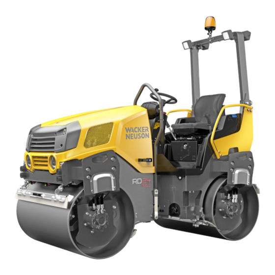
This instruction manual is valid for the following roller types: TANDEM ROLLER RD 24-100 US RD 24-100 O US RD 28-120 US RD 28-120 O US COMBINATION ROLLER RD 24-100 C US RD 28-120 C US BA RD24_RD28 en us 06...
This instruction manual is not a manual for extensive maintenance and repair work. Such work should be carried out by Wacker Neuson service or authorized specialists. The safety of the operator was one of the most important aspects taken into consideration when this machine was designed.
Foreword Introduction 1.00 Introduction 1.00.01 Preface to the instruction manual This chapter contains important instructions for the operating personnel on how to operate the machine and to use this instruction manual. This instruction manual helps you: To become familiar with the machine. To avoid malfunctions due to improper use.
Foreword Introduction 1.00.04 Modifications / reservations We are committed to provide you with correct and updated instruction manual. However, we cannot guarantee the correctness of all data given. To be able to keep pace with changing trends, it may be necessary to amend or modify the product and/or how it is operated without prior notice.
Foreword Introduction Example 15270 Legend Driver Engine compartment Descriptive text The drive lever [501] determines the driving direction and speed. Using the lever [520] you can adjust the pretension of the attenuation system to the driver's weight. 1.00.07 Signal words A signal word identifies a source of dangers and residual risks.
Foreword Documentation 1.01 Documentation This instruction manual is intended to make the operating personnel familiar with basic work steps / activities of and with the machine. The entire instruction manual consists of: Safety instructions Instruction manual of the machine Instruction manual of the diesel engine If necessary, additional information (e.
Foreword 1.02 1.02.01 Intended Use The machine represents state-of-the-art technology and complies with all valid safety regulations concerning its intended use at the time the machine was launched on the market. When designing the machine it was not possible to avoid foreseeable misuse or residual risks without restricting the machine's intended functionality.
Foreword 1.02.02 Abnormal use Any abnormal use or any misuse of the machine will void the manufacturer's warranty obligation, and the owner will bear the sole responsibility in this case. Abnormal uses shall be deemed to include: Non-compliance with this instruction manual. Operating errors by operating personnel not qualified or not instructed.
Foreword The machine may cause risk to the environment with: Improper operation. Operating supply items (lubricants etc.). Noise emission. Property damage may occur at the machine e.g. with: Improper operation. Non-compliance with operating and maintenance instructions. Improper operating supply items. Property damage may occur at further assets within the machine's operating area e.g.
Foreword Environmental protection 1.03 Environmental protection Packing materials, cleaning agents and used or residual operating supply items are to be disposed according to relevant environmental provisions at the building site using the recycling systems provided. 1.04 Disposal Conservation of nature is one of our major tasks. Properly disposed devices avoid negative impacts on human beings and the environment and allows re-using our precious resources.
Foreword Type plate 1.05 Type plate N O T E For machines without EC Conformity, neither an EC Declaration of Conformity nor a CE type plate can be issued. This is the case if, for example, the machine does not have a drum drive, drum brake or roll-over (ROPS) protection.
Page 20
Foreword Type plate 17236 Homologation (e.g. registration Designation number for use on public roads in Italy) Type Year of construction Vehicle identification number Engine power / nominal speed (VIN / PIN) Basic weight Operating weight Maximum operating weight Gross vehicle weight rating STVZO (only valid on public roads) Permissible axle load, front /...
Page 21
Foreword Type plate Type plate roll-over The roll-over protection, ROPS, approved by the manufacturer for this protection ROPS machine is marked by a type plate attached at the cabin / roll-over bar (see page 40). 17237 Series / type (part of the VIN / Cabin / ROPS identification PIN) number 1...
Foreword Noise and vibration requirements 1.06 Noise and vibration requirements The sound emission of the machine was measured according to the CE Sound Emission Directive in the version 2000/14/EC. The sound and vibration indications on the driver's seat correspond to the requirements of the CE Machinery Directive in the version 2006/42/EC.
Foreword Personnel 1.07 Personnel 1.07.01 Qualification and duties Operating personnel All activities at the machine must be carried out by authorised operating personnel only. In this instruction manual the term operating personnel refers to all authorised persons that are responsible for operating, maintaining, installing, setting up, cleaning, repairing or transporting the machine.
Page 24
Foreword Personnel Please adhere to the following instructions: Please drive the machine only if you are entirely familiarised with the operating and control elements and the method of operation. Please use this machine only according to its intended purpose. In case you detect any defects, such as at the safety equipment, that may affect the safe operation of the machine, please immediately notify the supervising body.
Foreword General safety instructions 1.08 General safety instructions Safety instructions The safety instructions are part of the instruction manual. Please make yourself familiar with these safety instructions prior to working with the machine. Regulations and Provisions In addition to this instruction manual, it is also necessary to adhere to all laws, standards, regulations and provisions applicable in the country of use and at the building site.
Foreword Danger zone 1.09 Danger zone N O T E The machine's danger zone is divided into the areas inactive and moving. Zone "inactive" 15272 If the machine is at a standstill and the diesel engine is switches off, the danger zone is defined as the area within 1 metre from the machine.
Foreword Loading and transporting 1.10 Loading and transporting Regulations and Provisions When loading rollers onto lorries, trailers or semitrailers, it is obligatory to secure the load properly. The laws, regulations, guidelines and standards applicable at the place of use must be observed. Sufficient knowledge about the loading of vehicles as well as about their behaviour under load are required for loading and transporting the machine.
Page 28
Foreword Loading and transporting Load securing Special notes Variant and variant may be combined. The lashing devices must not necessarily be arranged crosswise. Do not use any lashing device unless it is of sufficient dimension, bears the corresponding marking, and has been subjected to a valid inspection.
Page 29
Foreword Loading and transporting Crane loading Special notes The crane vehicle must be positioned on flat ground providing • the bearing capacity required while observing all relevant safety regulations. The crane's load table must correspond to the weight and the centre •...
Page 30
Foreword Loading and transporting Loading chart Diagram of the transport position Diagram of the centre of gravity specifications: 17757 17758 Lashing variant 1 17759 Weight class [t] Lashing force LC (μ=0.6) [daN] to 5.7 2000 Lashing variant 2 17760 Weight class [t] Lashing force LC (μ=0.6) [daN] to 5.7 2000...
Page 31
Foreword Loading and transporting Machine parameters Weight of machine [t] 1.5 t < m < 5.7 t Area of center of gravity [mm] = 778 - 1048 = 428 - 753 = 650 - 1030 Identification reference point: Centre drum, front left 17339 Interface parameters: Type of contact:...
Foreword Stickers on the machine 1.11 Stickers on the machine Below you will find all used stickers. You will find the precise arrangement of stickers in the spare parts catalogue. The safety manual contains the warning labels. 1.11.01 Warning labels M A R G I N Read documentation Read instruction manual and safety manual before you start working...
Page 33
Foreword Stickers on the machine M A R G I N V-belt Risk of trapping! Open belts or chains. With the machine running, serious injuries or fatality may be caused. Prior to maintenance work, shut down engine and remove ignition key. Wait until all machine components have come to a standstill.
Foreword Stickers on the machine M A R G I N Diesel Diesel tank! Use diesel with a sulphur content of less than 0.5%. Pay attention to standards. M A R G I N M A R G I N Safety strut Marking of a safety strut.
Page 35
Foreword Stickers on the machine M A R G I N Engine speed M A R G I N Water sprinkling M A R G I N Water tank filling M A R G I N Water tank outlet M A R G I N Additive sprinkling M A R G I N Water tank inlet of additive sprinkling...
Page 36
Foreword Stickers on the machine M A R G I N Hydraulic oil filling level M A R G I N Hydraulic oil reservoir inlet M A R G I N Hydraulic oil reservoir outlet M A R G I N Socket 12V M A R G I N Engine oil outlet...
Page 37
Foreword Stickers on the machine M A R G I N Inflation pressure Tyre without water filling M A R G I N Inflation pressure Tyre with water filling M A R G I N Guaranteed sound power level M A R G I N First-aid kit M A R G I N Expert inspection test badge...
Description Technical characteristics of the machine DESCRIPTION N O T E When working at the machine please always adhere to the instructions given in your Safety instructions! 000-01 2.00 Technical characteristics of the machine Transmission Hydrostatic all-wheel drive Infinitely variable Single lever operation Compaction system Dynamic oscillatory system due to vibration / oscillation...
Description General view of machine 2.01 General view of machine N O T E This operating manual applies to several types of this series. Therefore it is possible that these instructions include descriptions of operating elements not installed on your machine.
Description General view of machine 2.01.02 Control stand ROPS roll-over bar (folding) 17240 Handles Stacker for operating manual / first aid kit Steering column Operator's seat console Roll-over bar ROPS roll-over bar type plate Locking pin BA RD24_RD28 en us 06...
Description General view of machine 2.01.03 Drive unit / diesel engine 17810 Fuel system Oil gauge stick Oil inlet Diesel engine with drive units Air filter Coolant inlet Coolant level indicator 17811 Air filter Dust discharge valve Cooling system Diesel engine oil drain Exhaust system BA RD24_RD28 en us 06...
Description General view of machine 16521 Diesel engine type plate 2.01.04 Hydraulic oil supply 17812 Oil inlet Level indicator Hydraulic oil reservoir Oil outlet BA RD24_RD28 en us 06...
Description General view of machine 17813 Hydraulic oil filter 2.01.05 Electrical equipment Engine compartment 17346 Battery Battery isolating switch Main fuse BA RD24_RD28 en us 06...
Page 44
Description General view of machine Fuses 15453 Fuses Socket 15437 Socket 12 V BA RD24_RD28 en us 06...
Description General view of machine 2.01.06 Drive Roller drum scraper 17243 Scraper Scraper for roller drum and tyres 17368 Scraper BA RD24_RD28 en us 06...
Description General view of machine 2.01.07 Steering system 17244 Steering cylinder Articulated pendulum joint 2.01.08 Water system G, H, J, K 17245 Sprinkling nozzles Water tank filling Water tank Water outlet Water filter Water pump Additive sprinkling nozzles Additive tank Additive sprinkling water pump Additive tank outlet Inlet additive tank...
Description General view of instruments and operating elements 2.02 General view of instruments and operating elements N O T E All instruments and operating elements are marked by numbers. You will find a description in chapter 3 under the corresponding element. 000-04 N O T E Please observe chapter 6, too.
Page 49
Description General view of instruments and operating elements Steering column 17247 [310] Electrical system / engine start switch Driver's seat 15507 [520] Seat adjustment weight / [521] Seat adjustment forward - height backward [522] Seat adjustment backrest [525] Seat adjustment left - right BA RD24_RD28 en us 06...
Page 50
Description General view of instruments and operating elements Driver's seat, model C 17963 [520] Seat adjustment weight [521] Seat adjustment forward - backward [522] Seat backrest adjustment [525] Seat adjustment left - right Normal mode control unit 301 304 17248 [101] Hourmeter indicator [118] Display of diagnostic code [216] Pilot light, cold start assistance...
Page 51
Description General view of instruments and operating elements Driving control unit 17250 [*205] All-wheel lock pilot light [*219] Pilot light working spotlights [233] Driving light pilot lamp [303] Flashing indicator switch [305] Warning flasher switch [307] Driving light switch [*309] Working lights switch [*311] Rotating light switch Control unit vibration / oscillation...
Page 52
Description General view of instruments and operating elements Water sprinkling control unit 17251 [207] Water sprinkling pilot light [232] Pilot light sprinkling stage [317] Sprinkling switch [373] Switch sprinkling stage Control unit additive sprinkling 17252 [*318] Switch additive sprinkling (only if with combination roller equipped) BA RD24_RD28 en us 06...
Description General view of instruments and operating elements Warning lamps control unit 203 201 228 229 17253 [201] Charge current pilot light [202] Oil pressure pilot light [203] Air filter pilot light [228] Engine temperature pilot light [229] Oil temperature pilot light, hydraulic system 2.02.02 Drive unit / diesel engine...
Description General view of instruments and operating elements 2.02.03 Transmission Roller drum scraper 16377 [536] Locking device of scraper Scrapper tyres 16925 [536] Locking device of scraper BA RD24_RD28 en us 06...
Operation Instruments and operating elements OPERATION 3.00 Instruments and operating elements N O T E The instruments and operating elements are arranged in this section in ascending order according to their number. These numbers in squared brackets are used as a reference in the description of the elements.
Operation Instruments and operating elements 3.00.02 Pilot lights Charge current Flashing during operation indicates missing charging current. 0201-204 Engine oil pressure Flashing during operation indicates insufficient oil pressure. 0202-204 Air filter Flashing during operation indicates a clogged air filter cartridge. 0203-204 All-wheel lock If the four-wheel blocking is switched on, the pilot light illuminates and...
Page 57
Operation Instruments and operating elements Water sprinkling The pilot light illuminates when the water pump runs during sprinkling. 0207-204 Cold start assistance At an outside temperature below 10 °C (50 °F), preheat diesel engine with cold start assistance (switch [310] position II). After reaching start temperature, the indicator switches off;...
Page 58
Operation Instruments and operating elements Engine temperature Flashing during operation indicates improper engine temperature. 0228-205 Oil temperature of hydraulic system Flashing during operation indicates improper hydraulic oil temperature. 0229-200 Preselection vibrator vibration system, vibration / oscillation deactivated This pilot light indicates a pre-selected vibrator / oscillator in case of de- activated vibration / oscillation.
Operation Instruments and operating elements Driving light Pilot light illuminates if the lighting is switched on. 0233-200 Fuel filling level The fuel tank filling level is displayed by an illuminated pilot light. According to the level, a light point moves between 2/3, 1/3 and 1/10, correspondingly.
Page 60
Operation Instruments and operating elements EMERGENCY STOP WARNING Full braking! Danger of injuries due to strong braking force. Activate EMERGENCY STOP only in the event of danger. Do not use the EMERGENCY STOP as operation brake. 002-03 0302-205 Pressing the switch: stops the hydraulic drive, switches off the diesel engine, activates the hydraulic brakes...
Page 61
Operation Instruments and operating elements By pressing the switch you apply the parking brake or release it. Applied — PRESS (pilot light lights) Released — PRESS again N O T E The parking brake can only be released, if the drive lever [501] is locked in central position.
Page 62
Operation Instruments and operating elements Electrical system / engine start The switch (ignition key) supplies the electrical components with power, and starts and stops the diesel engine. 0-position Electrical system — OFF Diesel engine — STOP (key released) Position I Electrical system —...
Page 63
Operation Instruments and operating elements Preselecting vibration / oscillation Pressing the pushbutton preselects the vibration system in the front drum, in the rear drum, or in both drums. This pilot light (symbol without oscillation) indicates a pre-selected vibrator / oscillator in case of de-activated vibration / oscillation. Each actuation of the switch switches one step ahead.
Page 64
Operation Instruments and operating elements Vibration mode manual - automatic The operating mode for the vibration / oscillation is set with the switch. The vibrator / oscillator can be switched on or off manually or automatically. Manual — PRESS (upper pilot light illuminates) The vibration / oscillation can be switched on or off at any time with the switch on the multifunction handle [503].
Page 65
Operation Instruments and operating elements Battery isolating switch N OT IC E Voltage spikes! Damage or destruction of electrical components. Only interrupt the circuit at the battery isolating switch when the engine is at a standstill and when the electrical system is switched off! 004-03 0356-200...
Operation Instruments and operating elements 3.00.04 Sockets, lights Socket 12 V / cigarette lighter Cigarette lighter Press the cigarette lighter until it engages (spiral-wound filament is heated). After a short time the lighter springs out and can be removed from the socket. Socket 12 V Power can be taken off from the cigarette lighter socket using the special plug.
Page 67
Operation Instruments and operating elements Engine speed The speed of the diesel engine can be regulated between idling speed and maximum speed using the adjusting lever. The lever can be engaged in three positions. The lever can also be positioned between this positions.
Page 68
Operation Instruments and operating elements Seat adjustment weight In order to absorb impulsive machine movements using the installed attenuation system, this must be adjusted to the weight of the driver. N O T E The weight adjustment handle may only be pressed downwards during weight adjustment.
Page 69
Operation Instruments and operating elements Seat adjustment weight Only adjust the weight setting when the seat is unloaded. To do so, turn the lever into the corresponding position: Light driver's weight — position I Medium driver's weight — position II Heavy driver's weight —...
Page 70
Operation Instruments and operating elements Version: Roller drum down The scraper can be held away from the drum by a catch. The catch holds or releases the scraper according to the position of the locking lever [A]. Catch open — position I (Scraper lies on drum) Catch closed —...
Operation Prior to machine start 3.01 Prior to machine start General WARNING Operating errors! Risk of injury due to improper use. Prior to every start-up: Check the machine for operational and traffic safety. Read and adhere to the instruction manual and the safety manual. Ensure that there are no persons or objects in the danger zone of the machine.
Page 72
Operation Prior to machine start Control stand Safety belt 17369 Safety belt N O T E The driver must wear a safety belt while driving machines with a ROPS cab or a ROPS roll-over bar. 000-37 If the machine is provided with a safety belt, this belt needs to be inspected for wear or damage before starting the engine.
Operation Engine start 3.02 Engine start General The start sequence may only be continued for a maximum 20 seconds, otherwise the starter will overheat and be destroyed. There must be pauses between the individual starting processes in order to allow the staring motor to cool down.
Page 74
Operation Engine start Before driveaway WARNING Long stopping distance! A delay in braking caused by a highly viscous hydraulic oil can lead to serious injuries or death. In case of low external temperatures, in particular when below freezing, wait a few minutes after starting the engine until driveaway.
Operation Driving 3.03 Driving Driveaway 17254 Engine speed [504] — MAX Parking brake [304] — RELEASED (pilot light goes out) N O T E The parking brake can only be released, if the drive lever [501] is locked in central position. Prior to moving off actuate the signal horn [301] briefly.
Page 76
Operation Driving Driving Machine may only be operated from the operator platform. Seat contact switch WARNING Extended braking distance! A delay in the effect of the automatic application of the brakes can lead to serious injuries or death. Do not use the function of the seat contact switch to stop the machine.
Page 77
Operation Driving The machine is equipped with a hydraulic four-wheel drive, which is driven by a variable displacement pump. The blower output is fed to both hub motors in the drum. The driving power of the machine is used for the locomotion according to the surface conditions and the corresponding drift.
Operation Driving with vibration / oscillation 3.04 Driving with vibration / oscillation General WARNING Explosion! Risk of injury due to burns and moving parts. Prior to switching on the vibration function, it must be ensured that there are no lines laid in the underground. 002-19 WARNING Reduced road adhesion!
Page 79
Operation Driving with vibration / oscillation Vibration / oscillation 15541 Pressing pushbutton [316] preselects the vibration system in the front drum, in the rear drum, or in both drums. The control light (symbol without vibration) indicates a pre-selected but de-activated vibration system. Each actuation of the switch switches one step ahead.
Operation Stopping, switching off engine, leaving machine 3.05 Stopping, switching off engine, leaving machine WARNING Uncontrolled driving behaviour! Autonomous movement of the machine can lead to serious injuries or death. Switch off diesel engine even if you leave the operator platform only for short time.
Page 81
Operation Stopping, switching off engine, leaving machine Automatic engine stop If the machine is fitted with an automatic engine stop, under certain conditions, the diesel engine is switched off automatically after a fixed set time. Prerequisites: 1. Driving lever is locked in position 0. 2.
Operation Operation monitoring 3.06 Operation monitoring 3.06.01 Filling levels Pay attention to the filling level for operating supply items (fuel etc.). 1. Fill up tanks in time. 2. Never drive the machine until the fuel tank is empty. 3.06.02 Pilot lights 15433 Observe the control and indication instruments on the dashboard from time to time.
Operation Water sprinkling 3.07 Water sprinkling General The pressure sprinkling ensures a reliable moistening of the roller drums during blacktop works and thus prevents bituminous materials from adhering to the drums. An electric water pump supplies the sprinkling system with water so that the water consumption can be optimally adjusted to the deployment conditions using the installed automatic sprinkling.
Page 84
Operation Water sprinkling Sprinkler nozzle check when Requirement: engine is at a standstill 1. Engine stopped 2. EMERGENCY STOP [302] — position DOWN 3. Switch [310] — position I 4. Parking brake [304] — APPLIED 5. Driving lever [501] — max. to the FRONT 6.
Operation Additive sprinkling 3.08 Additive sprinkling General The additive sprinkling enables a moistening of the wheels with a separating compound. This prevents that bitumen sticks on tyres when laying blacktops. This is the only way to make a neat and even covering. The emulsion may only be mixed of parting agent concentrate and water according to the indications of the parting agent producer (Observe regulations for environment protection).
Operation Scraper 3.09 Scraper General 17243 The scrapers [A] are designed to remove clogging dirt from the surface of the roller drums / tyres when working on soft, adhesive ground. With grounds that are not clingy or with transporting operations the scrapers can be lifted away from the roller drums / tyres.
Operation Scraper 3.09.02 Roller drum scraper, down 16932 Attach scraper 1. Switch off diesel engine and remove ignition key. 2. Turn stop lever [536] to I position for a short time. Moving the scraper away 1. Switch off diesel engine and remove ignition key. 2.
Operation Track offset 3.10 Track offset General Compacting work along kerbs or similar borders cannot be carried out, or only in a limited way, without track movement of the drums. A track adjustment especially developed for this problem enables the machine to drive very precisely along such problem areas.
Operation Start with jump leads 3.11 Start with jump leads Preparation Observe precaution measures for handling batteries (see Safety instructions). Pay attention to the nominal voltage of the batteries. A discharged battery can freeze already at 0 °C (32 °F). It is essential that you defrost a frozen battery in a warm room before connecting it with jump leads.
Page 90
Operation Start with jump leads Removing leads 1. To prevent overloads in the electrical system, switch on an electrical component in the discharged vehicle (e.g. driving light) before removing the jump leads. 2. Remove the jump leads in reverse order. BA RD24_RD28 en us 06...
Operation Towing 3.12 Towing General WARNING Brake out of order! Unintentional rolling away of the machine can lead to serious injuries or death. Prior to releasing the brake, secure the machine against rolling away with wedges. 002-23 17260 Towing the machine requires sufficient knowledge about the functioning of the hydrostatic drive and about the operation of the spring accumulators.
Page 92
Operation Towing 1. Drive lever [501] — CENTRE 2. Shut down diesel engine, if still functional. 3. Secure machine against rolling away with wedges or blocks. 4. Interrupt frictional connection of the hydrostatic drive (see text below). 5. Disable parking brakes (see text below). 6.
Page 93
Operation Towing Putting parking brake out of operation 15496 The pretension of the spring-operated brakes may only be reduced when towing with a defective diesel engine or hydraulic system. 1. Loosen screw [A] and screw out by hand until a resistance can be noted (approximately 5 rotations).
Operation Driving on public roads 3.13 Driving on public roads 3.13.01 Applicable in the User's Country The laws, regulations, guidelines and standards applicable at the place of use must be observed. BA RD24_RD28 en us 06...
Maintenance General maintenance instructions MAINTENANCE N O T E When working at the machine please always adhere to the instructions given in your Safety instructions! 000-01 N O T E Please observe chapter 6, too. Here you find the description, operator control and maintenance of auxiliary equipment.
Maintenance General maintenance instructions 4.00.02 Maintenance overview N O T E For engine maintenance see instruction manual for diesel engine ( Lubricating oil change These intervals depend, e.g., on: intervals Lubricating oil quality Fuel sulphur content The mode in which the diesel engine is used Change lubricating oil after half the interval indicated, e.g., when at least one of the following conditions is true: Continuous ambient temperature below –10 °C (14 °F) or lubricating...
Maintenance General maintenance instructions Every 500 operating hours 500 h Replacing filter insert of pressure filter for see page 116 hydraulic system Checking damping elements see page 127 Checking wheel nuts / wheel bolts for tight- see page 120 ness Replacing valve cover seal Replacing filter cartridge for the fuel filter see page 106...
Maintenance General maintenance instructions Maintenance of the tyre mounting 1. Checking wheel nuts / wheel bolts for tightness. 4.00.04 Important information about maintenance work General Specialist knowledge is necessary for the execution of some inspection and maintenance works; these cannot be given in the scope of these operating instructions.
Page 99
Maintenance General maintenance instructions WARNING Explosion, acid! Risk of injury due to moving parts and caustic acids. Do not put any tools on the battery. 002-11 WARNING Fluids under pressure! Risk of injury due to fluids spurting out under pressure. Carry out maintenance works only with depressurized hydraulic systems.
Maintenance General maintenance instructions 4.00.05 Safety strut Applying safety strut A / B A / B 15460 1. Open bolt retainer [A] and remove together with the bolt [B]. 2. Turn coupling bar [C] to the opposed locking device and secure with the bolt [B].
Page 101
Maintenance General maintenance instructions Procedure Switch off diesel engine and remove ignition key. N O T E Maintain an after-running time of 2 minutes. 000-39 Disconnect battery, first negative then positive terminal. Connect negative terminal of the welding appliance in the vicinity of the weld.
Maintenance Chassis / safety features 4.01 Chassis / safety features 4.01.01 General Adhere to the following Check operating and safety instructions on the machine. Replace instructions: damaged and/or non-readable signs. Ensure that hinges and links move easily and lubricate lightly. Check the warning devices (signal horn, reflectors, back-up alarm, blinkers and warning flashers).
Maintenance Chassis / safety features 4.01.03 Checking EMERGENCY STOP function WARNING Full braking! Danger of injuries due to strong braking force. Activate EMERGENCY STOP only in the event of danger. Do not use the EMERGENCY STOP as operation brake. 002-03 17351 Function test when engine at Carry out functional tests with the diesel engine running and the work...
Maintenance Drive unit - diesel engine 4.02 Drive unit - diesel engine 4.02.01 General WARNING Inflammable fuel! Risk of injury due to fire and explosion. Do not smoke. No open fire. Do not breathe in fuel vapours. Catch spilling fuel or water sump, do not allow to seep away into the ground! 002-29 N OT I CE...
Maintenance Drive unit - diesel engine Lubricating oil change These intervals depend, e.g., on: intervals Lubricating oil quality Fuel sulphur content The mode in which the diesel engine is used Change lubricating oil after half the interval indicated, e.g., when at least one of the following conditions is true: Continuous ambient temperature below –10 °C (14 °F) or lubricating oil temperature below 60 °C (84 °F).
Maintenance Drive unit - diesel engine 4.02.03 Replacing filter cartridge for the fuel filter WARNING Inflammable fuel! Risk of injury due to fire and explosion. Do not smoke. No open fire. Do not breathe in fuel vapours. Catch spilling fuel or water sump, do not allow to seep away into the ground! 002-29 17816...
Maintenance Drive unit - diesel engine 4.02.04 Changing filter cartridge for the fuel prefilter WARNING Inflammable fuel! Risk of injury due to fire and explosion. Do not smoke. No open fire. Do not breathe in fuel vapours. Catch spilling fuel or water sump, do not allow to seep away into the ground! 002-29 15593...
Maintenance Drive unit - diesel engine N O T E Purging of the fuel system is performed by starting the diesel engine. For this, several starting attempts may be necessary. The starting process may last 20 seconds as a maximum; otherwise, the starter winding will be overheated and destroyed.
Maintenance Drive unit - diesel engine 4.02.06 Checking and replacing the air filter WARNING Exposed, rotating parts! Risk of injury due to rotating parts. Start the diesel engine only with closed engine hood resp. closed engine room doors. Ensure that there are no persons or objects in the danger zone of the machine.
Maintenance Drive unit - diesel engine Replacing the air filter 1. Switch off diesel engine and remove ignition key. cartridge 2. Allow machine to cool down under a temperature of 30 °C (86 °F). 3. Fold up clip [C]. 4. Remove dust container [D]. 5.
Maintenance Drive unit - diesel engine 4.02.08 Checking radiator 17356 Switch off diesel engine and remove ignition key. Allow machine to cool down to a temperature under 30 °C (86 °F). Check the cooling fins of the radiator for contamination. N O T E If the radiator is contaminated it must be cleaned thoroughly and immediately.
Maintenance Drive unit - diesel engine 4.02.10 Changing coolant WARNING Hot surface, hot fluids! Risk of burns due to hot surfaces and fluids. Prior to maintenance works, allow machine to cool down to a temperature under 30 °C (86 °F) . Do not touch hot machine parts.
Page 113
Maintenance Drive unit - diesel engine 14. Start the diesel engine and bring it to operating temperature (thermostat opens). 15. Switch off diesel engine and remove ignition key. 16. Check coolant level when the diesel motor is cold, fill up as necessary.
Maintenance Hydraulic oil supply 4.03 Hydraulic oil supply 4.03.01 General All lines, hoses and screwed connections must be checked for leaks and visible damage (at least once per year). Damaged parts must be replaced immediately. Further operation is inadmissible. Oil spurting out can lead to injuries and fire. Avoid subsequent damage! After a damage to the hydraulic system, with a foreign object having entered the oil circuit, the entire hydraulic system must be cleaned.
Maintenance Hydraulic oil supply 4.03.03 Changing hydraulic oil and ventilation filter WARNING Hot surface, hot fluids! Risk of burns due to hot surfaces and fluids. Prior to maintenance works, allow machine to cool down to a temperature under 30 °C (86 °F) . Do not touch hot machine parts.
Maintenance Hydraulic oil supply 1. Switch off diesel engine and remove ignition key. 2. Allow machine to cool down to a temperature under 30 °C (86 °F). 3. Unscrew oil drain screw [C] down on the oil tank and discharge the used oil drain into a provided receptacle.
Page 117
Maintenance Hydraulic oil supply 1. Switch off diesel engine and remove ignition key. 2. Allow machine to cool down to a temperature under 30 °C (86 °F). 3. Unscrew the cup-shaped housing [A]. 4. Unscrew the filter insert [B] from the filter head and replace with a new one.
Maintenance Drive 4.04 Drive 4.04.01 Checking drive lever 17357 Function test 1. Switch off diesel engine and remove ignition key. 2. Move the drive lever [501] forward and back completely. The drive lever must allow even movement in both directions without using excessive force.
Maintenance Drive N O T E Exchanging the scraper Drive the machine over an inspection pit in order to obtain easier access to the clamps to change the scraper. 1. Switch off diesel engine and remove ignition key. 2. Turn stop lever [536] to 0 position and move the scraper away. 3.
Maintenance Drive 4.04.04 Lubricating scraper stop lever 16938 1. Switch off diesel engine and remove ignition key. 2. Clean off dirt adhering to the catch [536]. 3. Turn stop lever [536] to I position. 4. Lubricate the guide bolt of the locking lever with oil at positions [A]. 5.
Maintenance Drive 4.04.06 Checking air pressure in the tyres WARNING Explosion, fluids under pressure! Risk of injury due to flying parts and fluids spurting out under pressure. Change damaged tyres. When filling, do not exceed the values of the specified air pressure. Use only suitable filling devices with a pressure indicator.
Maintenance Drive 4.04.07 Wheel change N O T E After every wheel change, check the firm seat of every wheel nut / wheel lug bolt after 50 operating hours. 000-26 Preparation Only persons familiar with changing tyres and aware of dangers are allowed to change the tyres.
Maintenance Steering system 4.05 Steering system 4.05.01 General Any work in the danger zone of the articulated steering may only be performed with the engine at a standstill and with the electrical system switched off! Furthermore, the safety strut must be latched. 4.05.02 Lubricating pivoted bearing WARNING...
Maintenance Steering system 4.05.03 Lubricating steering cylinder bolt WARNING Uncontrolled movements! If the machine rolls away, this can lead to serious injuries or death. Secure machine against rolling away. Prior to maintenance works, apply the safety strut in the hazard area.
Maintenance Sprinkling 4.06 Sprinkling 4.06.01 General A high-volume, rustproof water filter, arranged upstream the water pump, prevents a premature contamination of pump, lines and spraying nozzles, thus ensuring a trouble-free operation. Its maintenance depends on the purity of the water used. Only use clean water! 4.06.02 Cleaning water sprinkling unit 15489...
Maintenance Sprinkling 4.06.03 Cleaning filter for water sprinkling 15564 1. Switch off diesel engine and remove ignition key. 2. Unscrew filter head [E] at the water tank and remove it together with the compression spring (observe gasket ring on filter head). 3.
Maintenance Vibration / oscillation 4.07 Vibration / oscillation 4.07.01 Checking damping elements 15516 1. Switch off diesel engine and remove ignition key. 2. Check the damping elements [A] of the roller drum suspension for cracks. Replace damaged damping elements by new ones. 4.07.02 Changing the toothed belt for the oscillation drive 16939...
Tables Technical data TABLES N O T E When working at the machine please always adhere to the instructions given in your Safety instructions! 000-01 5.00 Technical data 5.00.01 Engine oil M A R G I N Engine oil grade Do not operate the diesel engine unless using engine oil as specified in the consumables indications see page...
Tables Technical data 5.00.02 Hydraulic oil The most important characteristic of a pressure fluid is its viscosity. Compliance with the permissible viscosity ranges is especially important for pumps and hydraulic motors. Too high a viscosity leads to cavitation, too low a viscosity increases leak losses = overheating, and thus a further fall in the viscosity. In the end, the limit of the lubricating capability is reached.
You can request for these instructions at Wacker Neuson Customer service. All filters in the oil circuit are to be replaced 50 operating hours after oil replacement. After that, the filter change intervals given in this instructions apply again.
ISO VG 68 tropical HEES Synthetic, saturated ester ISO VG 100 extreme heat (ISO-VG: viscosity grade). Special oil Only Wacker Neuson special oil is admissible. Gear box oil with Limited-Slip-Additions. API GL-5 SAE 85W-90 The oil quality must correspond to the API classification.
Page 132
Tables Technical data Starting torques for regular type screw threads Starting torques MA (Nm) Threads 10.9 12.9 16.5 1120 1000 1400 1650 1350 1900 2250 Starting torques for fine threads Starting torques MA (Nm) Threads 10.9 12.9 M8x1 24.5 M10x1.25 M12x1.25 M12x1.5 M14x1.5...
The version valid at the time the technical data was prepared for this version of the manual was used (see impressum: change date). Other values may apply if modifications are made to the machine in the course of its further development. 000-30 5.01.01 RD 24-100 Designation Value Unit Dimensions and weights...
Page 134
Tables Technical data Designation Value Unit Capacities Fuel 42.00 l Engine oil (for oil change) 7.00 l Coolant of diesel engine 8.00 l Hydraulic oil 26.00 l Water sprinkling 180.00 l Sound power level Sound power level L , guaranteed 106 dB(A) Sound power level L , representative measurement...
Tables Technical data 5.01.02 RD 24-100 O Designation Value Unit Dimensions and weights Unladen weight without ROPS roll-over bar 2284 kg Operating weight with ROPS roll-over bar 2525 kg Axle load front / rear 1205 / 1320 kg Working width / max. working width...
Page 136
Tables Technical data Designation Value Unit Capacities Fuel 42.00 l Engine oil (for oil change) 7.00 l Coolant of diesel engine 8.00 l Hydraulic oil 26.00 l Water sprinkling 180.00 l Sound power level Sound power level L , guaranteed 106 dB(A) Sound power level L , representative measurement...
Tables Technical data 5.01.03 RD 24-100 C Designation Value Unit Dimensions and weights Unladen weight without ROPS roll-over bar 2134 kg Operating weight with ROPS roll-over bar 2385 kg Axle load front / rear 1210 / 1175 kg Wheel load per tyre 293.75 kg...
Page 138
Tables Technical data Designation Value Unit Capacities Fuel 42.00 l Engine oil (for oil change) 7.00 l Coolant of diesel engine 8.00 l Hydraulic oil 26.00 l Water sprinkling 180.00 l Additive sprinkling 18.00 l Sound power level Sound power level L , guaranteed 106 dB(A) Sound power level L...
Page 139
Tables Technical data 5.01.04 RD 28-120 Designation Value Unit Dimensions and weights Unladen weight without ROPS roll-over bar 2454 kg Operating weight with ROPS roll-over bar 2695 kg Axle load front / rear 1335 / 1360 kg Working width / max. working width 1200 / 1250 mm Turning radius inside / outside 2370 / 3570 mm...
Page 140
Tables Technical data Designation Value Unit Capacities Fuel 42.00 l Engine oil (for oil change) 7.00 l Coolant of diesel engine 8.00 l Hydraulic oil 26.00 l Water sprinkling 180.00 l Sound power level Sound power level L , guaranteed 106 dB(A) Sound power level L , representative measurement...
Tables Technical data 5.01.05 RD 28-120 O Designation Value Unit Dimensions and weights Unladen weight without ROPS roll-over bar 2514 kg Operating weight with ROPS roll-over bar 2755 kg Axle load front / rear 1335 / 1420 kg Working width / max. working width 1000 / 1050 mm Turning radius inside / outside 2370 / 3570 mm...
Page 142
Tables Technical data Designation Value Unit Capacities Fuel 42.00 l Engine oil (for oil change) 7.00 l Coolant of diesel engine 8.00 l Hydraulic oil 26.00 l Water sprinkling 180.00 l Sound power level Sound power level L , guaranteed 106 dB(A) Sound power level L , representative measurement...
Tables Technical data 5.01.06 RD 28-120 C Designation Value Unit Dimensions and weights Unladen weight without ROPS roll-over bar 2344 kg Operating weight with ROPS roll-over bar 2595 kg Axle load front / rear 1340 / 1255 kg Wheel load per tyre 313.75 kg Working width / max.
Page 144
Tables Technical data Designation Value Unit Capacities Fuel 42.00 l Engine oil (for oil change) 7.00 l Coolant of diesel engine 8.00 l Hydraulic oil 26.00 l Water sprinkling 180.00 l Additive sprinkling 18.00 l Sound power level Sound power level L , guaranteed 106 dB(A) Sound power level L...
Tables Fuses 5.03 Fuses WARNING Fire hazard if fuses are not inserted correctly! Insert only specified fuses (no fuses with a higher amperage!). Do not install a bypass to the fuses. 002-46 Fuses Position Fuse assignment Fuse Main fuse on the battery 80 A All-wheel lock Time relay cold start assistance...
Assembly Instructions and Auxiliary Devices ROPS roll-over bar ASSEMBLY INSTRUCTIONS AND AUXILIARY DEVICES N O T E When working at the machine please always adhere to the instructions given in your Safety instructions! 000-01 N O T E Please also consider the parts included in the scope of supply. They may be different from the parts list content indicated here due to further developments in the product.
Page 150
Assembly Instructions and Auxiliary Devices ROPS roll-over bar Assembly instructions ROPS WARNING roll-over bar High self-weight of machine! If the machine overturns backwards, forwards or sideways there is a danger of serious injuries or death. Operate machine only with the ROPS safety device installed according to instructions.
Assembly Instructions and Auxiliary Devices Rotating light removable 6.01 Rotating light removable General When switched on, the rotating light warns against possible hazards caused by the machine. After parking the machine, the rotating light [A] can be removed from the contact tube [B] and be stowed inside the cab. 6.01.01 Overview 17751...
Assembly Instructions and Auxiliary Devices Rotating light removable Switching on and off rotating The rotating light must be placed on the outside of the machine and set to light on at all times during operation. 17918 Pressing the switch turns the rotating light on or off. On —...
Assembly Instructions and Auxiliary Devices Rotating light removable Removing rotating light 17755 1. Unscrew the clamping screw [D] and slide the rotating light [C] off the contact tube [B]. 2. Close the contact tube [B] with the protective cap [A]. 3.
Page 154
Assembly Instructions and Auxiliary Devices Rotating light removable Care 17756 Dirt can impair the function of the rotating light. Therefore keep the rotating light clean! To clean the rotating light [C], use only a sponge and soap water. Do not clean the rotating light with a water jet or high-pressure cleaner.
Assembly Instructions and Auxiliary Devices Injection of antifreeze for the sprinkler 6.02 Injection of antifreeze for the sprinkler General During the part of the year in which there is a danger of frost at night, the sprinkling system pipes can be filled with an antifreeze solution. This prevents the system from being damaged by frost.
Page 156
Assembly Instructions and Auxiliary Devices Injection of antifreeze for the sprinkler Fill the piping system 16969 1. Shut down the diesel engine. 2. Switch the sprinkler to spray nozzle control when the machine is at a standstill. 3. Take the injection hose [A] out of its holder, and clean the end of the hose if necessary.
Page 157
Wacker Neuson Produktion GmbH & Co. KG Wackerstraße 6 85084 Reichertshofen, Germany www.wackerneuson.com Tel.: +49 (0) 8453 340 32 00 Order no. 5100026259 Language en us...
Need help?
Do you have a question about the RD 24 and is the answer not in the manual?
Questions and answers