Advertisement
GENERAL SAFETY RULES

Your new tool has been engineered and manufactured to WEN's highest standards for dependability, ease of operation, and operator safety. When properly cared for, this product will supply you years of rugged, trouble-free performance. Pay close attention to the rules for safe operation, warnings, and cautions. If you use your tool properly and for intended purpose, you will enjoy years of safe, reliable service.
Safety is a combination of common sense, staying alert and knowing how your item works. SAVE THESE SAFETY INSTRUCTIONS.

To avoid mistakes and serious injury, do not plug in your tool until the following steps have been read and understood.
- READ and become familiar with this entire instruction manual. LEARN the tool's applications, limitations, and possible hazards.
- AVOID DANGEROUS CONDITIONS. Do not use power tools in wet/damp areas or expose them to rain. Keep work areas well lit.
- DO NOT use power tools in the presence of flammable liquids or gases.
- ALWAYS keep your work area clean, uncluttered, and well lit. DO NOT work on floor surfaces that are slippery with sawdust or wax.
- KEEP BYSTANDERS AT A SAFE DISTANCE from the work area, especially when the tool is operating. NEVER allow children or pets near the tool.
- DO NOT FORCE THE TOOL to do a job for which it was not designed.
- DRESS FOR SAFETY. Do not wear loose clothing, gloves, neckties, or jewelry (rings, watches, etc.) when operating the tool. Inappropriate clothing and items can get caught in moving parts and draw you in. ALWAYS wear non-slip footwear and tie back long hair.
- WEAR A FACE MASK OR DUST MASK to fight the dust produced by sawing operations.
![]()
Dust generated from certain materials can be hazardous to your health. Always operate the tool in a well-ventilated area and provide for proper dust removal. Use dust collection systems whenever possible. - ALWAYS remove the power cord plug from the electrical outlet when making adjustments, changing parts, cleaning, or working on the tool.
- KEEP GUARDS IN PLACE AND IN WORKING ORDER.
- AVOID ACCIDENTAL START-UPS. Make sure the power switch is in the OFF position before plugging in the power cord.
- REMOVE ADJUSTMENT TOOLS. Always make sure all adjustment tools are removed from the saw before turning it on.
- NEVER LEAVE A RUNNING TOOL UNATTENDED. Turn the power switch to OFF. Do not leave the tool until it has come to a complete stop.
- NEVER STAND ON A TOOL. Serious injury could result if the tool tips or is accidentally hit. DO NOT store anything above or near the tool.
- DO NOT OVERREACH. Keep proper footing and balance at all times. Wear oil-resistant rubber-soled footwear. Keep the floor clear of oil, scrap, and other debris.
- MAINTAIN TOOLS PROPERLY. ALWAYS keep tools clean and in good working order. Follow instructions for lubricating and changing accessories.
- CHECK FOR DAMAGED PARTS. Check for alignment of moving parts, jamming, breakage, improper mounting, or any other conditions that may affect the tool's operation. Any part that is damaged should be properly repaired or replaced before use.
- MAKE THE WORKSHOP CHILDPROOF. Use padlocks and master switches and ALWAYS remove starter keys.
- DO NOT operate the tool if you are under the influence of drugs, alcohol, or medication that may affect your ability to properly use the tool.
- USE SAFETY GOGGLES AT ALL TIMES that comply with ANSI Z87.1. Normal safety glasses only have impact resistant lenses and are not designed for safety. Wear a face or dust mask when working in a dusty environment. Use ear protection such as plugs or muffs during extended periods of operation.
SPECIFIC RULES FOR DRILL PRESS
Do not operate this tool until it is completely assembled and installed according to the instructions.
- Never turn the drill press on until the table is clear of all foreign objects (tools, scraps, etc.).
- Always keep hands and fingers away from the drill bit.
- Do not drill materials without a flat surface unless a suitable support is used (clamp or vice).
- Never start the drill press with the drill bit pressed against the workpiece.
- Make sure the table lock is tightened before starting the drill press.
- Never layout, assemble, or set-up any work on the table while the drill is on.
- Make sure the drill bit is securely locked in the chuck.
- Make sure the chuck key is removed from the chuck before turning power on.
- Adjust the table or depth stop to avoid drilling into the table.
- Always stop the drill before removing scrap pieces from the table.
- Use clamps or a vise to secure a workpiece to the table. This will prevent the workpiece from rotating with the drill bit.
- Do not wear gloves when operating a drill press.
- Set the drill press to the speed that is appropriate for the material being drilled.
- If any part of the drill press is missing/damaged or if the electrical components fail to perform properly, shut the power OFF and unplug the drill press. Replace missing, damaged or failed parts before resuming operation.
- Before leaving the machine, shut the power off, remove the drill bit and clean the table.
ELECTRICAL INFORMATION
GROUNDING INSTRUCTIONS
IN THE EVENT OF A MALFUNCTION OR BREAKDOWN, grounding provides the path of least resistance for an electric current and reduces the risk of electric shock. This tool is equipped with an electric cord that has an equipment grounding conductor and a grounding plug. The plug MUST be plugged into a matching outlet that is properly installed and grounded in accordance with ALL local codes and ordinances.
DO NOT MODIFY THE PLUG PROVIDED. If it will not fit the outlet, have the proper outlet installed by a licensed electrician.
IMPROPER CONNECTION of the equipment grounding conductor can result in electric shock. The conductor with the green insulation (with or without yellow stripes) is the equipment grounding conductor. If repair or replacement of the electric cord or plug is necessary, DO NOT connect the equipment grounding conductor to a live terminal.
CHECK with a licensed electrician or service personnel if you do not completely understand the grounding instructions or whether the tool is properly grounded.
USE ONLY THREE-WIRE EXTENSION CORDS that have three-pronged plugs and outlets that accept the tool's plug as shown in Fig. A. Repair or replace a damaged or worn cord immediately.


In all cases, make certain the outlet in question is properly grounded. If you are not sure, have a licensed electrician check the outlet.
This tool is for indoor use only. Do not expose to rain or use in damp locations.
GUIDELINES FOR USING EXTENSION CORDS
Make sure your extension cord is in good condition. When using an extension cord, be sure to use one heavy enough to carry the current your product will draw. An undersized cord will cause a drop in line voltage resulting in loss of power and overheating. The table below shows the correct size to be used according to cord length and nameplate ampere rating. When in doubt, use a heavier cord. The smaller the gauge number, the heavier the cord.
| AMPERAGE | REQUIRED GAUGE FOR EXTENSION CORDS | |||
| 25 ft. | 50 ft. | 100 ft. | 150 ft. | |
| 8.6 A | 18 gauge | 16 gauge | 14 gauge | 12 gauge |
Make sure your extension cord is properly wired and in good condition. Always replace a damaged extension cord or have it repaired by a qualified person before using it.
Protect your extension cords from sharp objects, excessive heat and damp/wet areas.
 Use a separate electrical circuit for your tools. This circuit must not be less than a #12 wire and should be protected with a 15 A time-delayed fuse. Before connecting the motor to the power line, make sure the switch is in the OFF position and the electric current is rated the same as the current stamped on the motor nameplate. Running at a lower voltage will damage the motor.
This tool must be grounded while in use to protect the operator from electric shock.
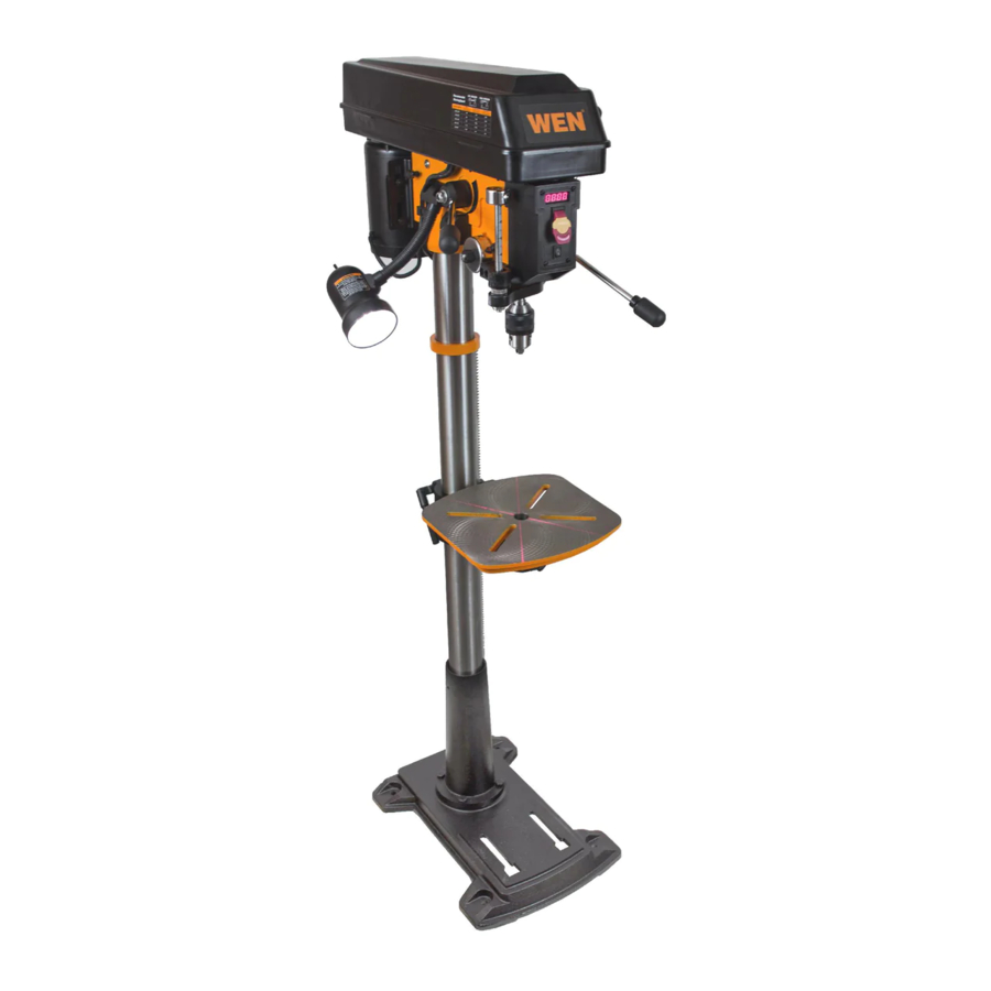
KNOW YOUR DRILL PRESS

- Digital Speed Readout
- ON/OFF Switch
- Depth Scale
- Chuck
- Table
- Laser Switch
- Feed Handles
- Pulley Cover Knob
- Pulley Cover
- Column
- Rack
- Crank Handle
- Column Base
- Base
- Table Lock Handle
- Bevel Lock Bolt
- Location Pin
- Bevel Scale
- Table Support Lock Handle
- Speed Control Handle
- LED Worklight Switch
- Power Cord
- Tension Knob
- Lock Handle
ASSEMBLY AND ADJUSTMENTS
UNPACKING (Fig. 2)
Unpack the drill press and all of its parts. Compare against the list below. Do not discard the carton or any packaging until the drill press is completely assembled.
To protect the drill press from moisture, a protective coating has been applied to the machine's surfaces. Remove this coating with a soft cloth moistened with kerosene or WD-40®. Do not use acetone, gasoline, or lacquer thinner to clean. Apply a coat of good paste wax to the table and column. Wipe all parts with a clean dry cloth.

- Head/Motor Assembly
- Column Assembly
- Table
- Base
- Hex Keys - 3, 4, 5
- Table Support Lock Handle
- Table Lock Handle
- Bolt M12 X 35
- Chuck
- Chuck Arbor
- Chuck Key
- Feed Handle
- Speed Handle
- Wedge
- Crank Handle
If any part is missing or damaged, do not plug the drill press in until the missing or damaged part is repaired or replaced.
The column assembly (column, column support, rack, rack collar, and table support bracket) must be attached to the base. The table and table support handles must be attached to the table support bracket. The motor housing must be attached to the column.
Tools needed for assembly
- Adjustable wrench
- screwdriver
- Hammer and block of wood
COLUMN ASSEMBLY TO BASE (Fig. 3)

- Place the column tube (1) on the base (2), aligning the column support holes to the base holes.
- Install a hex head bolt (3) in each column support hole and tighten bolts using the adjustable wrench.
TABLE TO TABLE SUPPORT BRACKET (Fig. 4)

- Place the crank handle (1) onto the shaft (2) of the table bracket so the flat of the shaft is under the set screw (3). Tighten the set screw.
- Thread the table lock handle (4) into the front of the table support bracket.
- Thread the table support lock handle into the rear of the table support bracket (not shown).
- Position the table (5) in the same direction as the base. Install the table and tighten the table lock handle (4) and support lock handle.
DRILL PRESS HEAD TO COLUMN (Fig. 5)
The drill press head is heavy. To avoid injury, two people should lift it into position.

- Carefully lift the drill press head assembly (1) and position it over the column (2).
- Place the mounting opening (3) on the drill press head over the top of the column. Make sure the drill press head is seated properly on the column.
- Align the direction of the drill press head with the direction of the base and the table.
- Tighten the set screw (4) using a hex key.
FEED HANDLES (Fig. 6)

- Insert the three speed handles (1) into the threaded openings on the feed hub (2).
- Manually tighten handles into openings.
Note: When using the drill press, one or two of the feed handles may be removed if an unusually-shaped workpiece interferes with handle rotation.
SPEED HANDLE (Fig. 7)

- Insert the feed handle (1) into the threaded opening on the speed hub (2).
- Manually tighten handle into opening.
MOUNT THE DRILL PRESS (Fig. 8)

The drill press must be securely fastened through the mounting holes to a stand or workbench with heavy-duty fasteners. This will prevent the drill press from tipping over, sliding, or walking during operation.
If the stand or workbench has a tendency to move during operation, fasten the workbench securely to the floor.
LED BULB
A LED bulb has been assembled in the socket of the head.
To reduce risk of fire, DO NOT use a light bulb greater than 40 watts. When changing the light bulb, always check that the power switch is in the OFF position and the plug is disconnected from its power source.
INSTALL THE CHUCK (Fig. 9)

- Inspect and clean the taper hole in the chuck and the spindle. Remove all grease, coatings, and particles from the chuck and spindle surfaces with a clean cloth.
- Open the chuck jaws by manually turning the chuck barrel clockwise. Make sure the jaws are completely recessed inside the chuck.
- Insert the chuck arbor into the opening at the top of the chuck.
- Seat the chuck and chuck arbor on the spindle by placing a block drive the chuck into the spindle.
REMOVE THE CHUCK (Fig. 10)

- Turn the feed handles (1) to lower the chuck to the lowest position.
- Slide the wedge into the opening in the quill. Tap on the wedge using a hammer (not included). The chuck and arbor will drop out.
Note: To avoid possible damage to the drill or chuck, be prepared to catch the chuck as it falls.
RAISE OR LOWER THE TABLE (Fig. 11)

- Loosen the support lock handle (1) and turn the crank handle (2) until the table is at the desired height.
- Tighten the support lock handle before drilling.
ROTATE THE TABLE (Fig. 11)
- Loosen the support lock handle (1) and turn the table around the column to the desired position.
Note: The rack should rotate around the column with the table support bracket. If the rack binds and does not rotate, slightly loosen the set screw in the rack collar. - Tighten the support lock before drilling.
TILT THE TABLE (Fig. 12)

- Rotate the table clockwise with the fork wrench. Pull out the location pin. Put the location pin and nut in suitable area.
- Rotate the bolt (1) counterclockwise with a wrench to loosen it.
- Adjuste the angle of the table.
- Tighten the bolt with fork wrench.
ADJUST THE TABLE TO BE HORIZONTAL
- Rotate the bolt (1) counterclockwise with a wrench to loosen it.
- Rotate the table to 0˚.
- Hit the location pin (2) into the location hole in the table support with a hammer.
- Tighten the nut of the location pin (2) slightly.
- Lock the bolt (1) with wrench.
To avoid injury, make sure the chuck key is removed from the chuck before starting any drilling operation.
INSTALLING A DRILL BIT (Fig. 13)

- Place the chuck key (1) into the side keyhole of the chuck (2), meshing the key with the gear teeth.
- Turn the chuck key counterclockwise to open the chuck jaws (3).
- Insert a drill bit (4) into the chuck far enough to obtain the maximum grip of the chuck jaws.
- Center the drill bit in the chuck jaws before the final tightening of the chuck.
- Tighten the chuck jaws using the chuck key to ensure that the drill bit will not slip while drilling.
- Remove the chuck key.
SQUARING THE TABLE TO THE DRILL BIT (Fig. 14)

- Insert a 3" long drill bit (1) into the chuck (2) and tighten the jaws with the chuck key.
- Raise the table with the crank handle (3). Lock the table (4) approximately 1" below the drill bit.
- Place a combination square (5; not included) on the table as shown, placing the long straight edge of the combination square against the drill bit. Make sure the drill bit is parallel/aligned exactly to the straight edge of the square.
- If an adjustment is needed, loosen the bevel lock bolt (6) with a wrench.
- Tilt the table slightly, until the combination straight edge is aligned perfectly with the drill bit.
- Tighten the bevel lock when square.
Note: Adjustments for the correct function of your drill press return spring have been done by the factory. Please do not modify them. However, prolonged use of the drill press may make some readjustments necessary.
ADJUSTING THE LASER (Fig. 15 and 16)
Do not stare directly at the laser beam. Please observe all safety rules.

- Never aim the beam at a person or an object other than the workpiece.
- Do not project the laser beam into the eyes of others.
- Always make sure the laser beam is aimed at a workpiece that does not possess reflective surfaces, as the laser beam could project into your eyes or the eyes of others.
- Place a workpiece on the table.
- Turn the laser switch (1) to the ON position.
- Lower the drill bit to meet the workpiece (2). The two laser lines should cross where the drill meets the workpiece.
- If the laser needs to be adjusted:
- Using a 3 mm hex key, turn the laser adjustment set screws (3) counterclockwise.
- Rotate the laser light housing (4) until the two laser lines intersect where the drill meets the workpiece.
DO NOT stare directly at the laser lines. - Re-tighten the adjustment set screws (3).
SPINDLE RETURN SPRING (Fig. 17)
The spindle is equipped with an auto-return mechanism. The main components are a spring and a notched housing. The spring was properly adjusted at the factory and should not be readjusted unless absolutely necessary.

- Unplug the drill press.
- Place a screwdriver into the loop (1) to hold the spring in place.
- Loosen the two housing nuts (2) approximately 1/4" (6 mm). Do not remove the nuts from the threaded shaft. Do not allow the spring or spring housing to slip out of control.
- While firmly holding the spring housing (3), carefully pull the spring housing out until it clears the raised notch (4).
- Turn the housing so that the next notch (5) is engaged with the raised notch (4).
- To increase the spindle return tension, turn the spring housing counter-clockwise.
- To decrease the tension, turn the spring housing clockwise.
- Tighten the two housing nuts. Do not overtighten the two nuts. If the nuts are tightened too much, the movement of the spindle and feed handles will become sluggish.
ANGULAR "PLAY" OF THE SPINDLE (Fig. 18)
Move the spindle to the lowest downward position and hold in place. Try to make the spindle revolve around its axis while also moving it with a side motion. If there is too much "play", proceed as follows:

- Loosen the lock nut (1).
- Without obstructing the upward and downward motion of the spindle, turn the screw (2) clockwise to eliminate the "play." Note: A little bit of "play" is normal.
- Tighten the lock nut (1).
REPLACING THE BELT (Fig. 19)

Disconnect the drill press from the power source before replacing the belt.
Belt tension and drill press speed is controlled by automatic adjustments made to the diameter of the front spindle when the drive handle is moved.
Note: See information on the variable speed function of this drill press.
- Remove the screw that secures the housing cover (1). Open the housing cover.
- Remove the belt (2) from the housing cover if it is broken. If it is not broken, but is too stretched to operate correctly, work the belt off the drive (motor) spindle (3). Then remove the belt from the front spindle (4).
- Replace the belt by putting a new belt over the front spindle (4) and carefully sliding the belt over the drive (motor) spindle (3).
Do not change the drive speed when the drill press is turned off.
OPERATION
DRILL PRESS ON/OFF SWITCH (Fig. 20)

- To turn the drill press ON, insert the yellow safety key (1) into the switch housing (2). As a safety feature, the switch cannot be turned ON without the safety key.
- Flip the switch upward to the ON position.
- To turn the drill press OFF, flip the switch downward.
- To lock the switch in the OFF position, remove the safety key (1) from the switch. Store the safety key in a safe place.
LIGHT AND LASER LINE ON/OFF SWITCHES (Fig. 20)
The light switch (3) is located on the lamp cover.
The laser switch (4) is located below the ON/OFF switch on the right.
POSITION THE TABLE AND WORKPIECE (Fig. 21)

Always place a piece of backup material (1) (wood, plywood, etc.) on the table underneath the workpiece (2). This will prevent splintering on the underside of the workpiece as the drill bit breaks through. To keep the material from spinning out of control, it must contact the left side (3) of the column as illustrated, or be clamped (4; not included) to the table.
Note: For small workpieces that cannot be clamped to the table, use a drill press vise (not included). The vise must be clamped or bolted to the table to avoid injury.
GENERAL DRILLING GUIDELINES - DRILLING A HOLE
To prevent the workpiece and the backup material from slipping from your hand while drilling, position the workpiece and backup material to the left side of the column. If the workpiece and the backup material are not long enough to reach the column, clamp the workpiece and backup material to the table. Failure to do this could result in personal injury.
- Mark where you want to drill in workpiece by using a center punch or a sharp nail or turn ON the laser to mark your drilling point.
- Before turning the drill press ON, turn the feed handles to bring the drill bit down. Line the drill bit tip up with the mark. Clamp the workpiece in place.
- Turn ON the drill press and pull down on the feed handles with the appropriate force needed to allow the drill bit to drill the material.
Note: Feeding too slowly might cause the drill bit to turn in the chuck. Feeding too rapidly might stop the motor, cause the belt to slip, force the workpiece loose, or break the drill bit. Practice with scrap material to get the feel of the machine before attempting to do any drilling operation.
ADJUST THE DRILLING DEPTH (Fig. 22)

The depth gauge controls the maximum distance the drill bit will move up or 1 down.
To stop the drill bit at a pre-measured depth, loosen the depth scale knob (1) by push button (2) until the bottom of the knob is aligned with the desired depth mark (3) on the gauge scale.
Drilling an unmeasured blind hole (not all the way through the workpiece) to a given depth can be done using either the depth scale method or the workpiece method.
DEPTH SCALE METHOD (Fig. 22)
- Make sure the 0 (" or mm) mark on the depth gauge rests at the top edge of the metal support (4) when the quill is fully retracted.
- Put the workpiece on the table and raise the table until the tip of the drill bit just touches the top of the workpiece. Lock the table in place.
- Determine the drill depth for this workpiece.
- Rotate the depth knob (2) until it is aligned with the desired depth mark (3) (for example, 1") on the gauge scale.
- The chuck will be stopped at the distance selected on the depth scale.
WORKPIECE METHOD (Fig. 22 and 23)

- Mark the desired depth (5) of the drill hole on the side of the workpiece.
- With the drill press in the OFF position, bring the drill bit (6) down until the tip is even with the mark.
- Holding the feed handles at this position, rotate the depth knob (2) until it meets the metal support.
- The chuck and the drill bit will now be stopped at the distance selected on the depth scale.
DRILLING SPEEDS
There are a few important factors to keep in mind when determining the best drilling speed:
- Material type
- Hole size
- Drill bit or cutter type
- Quality desired
Smaller drill bits require greater speed than larger drill bits. Softer materials require greater speed than harder materials. See recommended speeds for particular materials.
DRILLING METAL
- Use metal-piercing twist drill bits.
- It is always necessary to lubricate the tip of the drill with oil to prevent overheating of the drill bit.
- All metal workpieces should be clamped down securely. Any tilting, twisting, or shifting causes a rough drill hole, and increases the potential of drill bit breakage.
- Never hold a metal workpiece with your bare hands. The cutting edge of the drill bit may seize the workpiece and throw it, causing serious injury. The drill bit will break if the metal piece suddenly hits the column.
- If the metal is flat, clamp a piece of wood under it to prevent turning. If it cannot be laid flat on the table, then it should be blocked and clamped.
DRILLING WOOD
- Brad point bits are preferred. Metal piercing twist bits may be used on wood.
- Do not use auger bits. Auger bits turn so rapidly that they can lift the workpiece off of the table and whirl it around.
- Always protect the drill bit by positioning the table so that the drill bit will enter the center hole when drilling through the workpiece.
- To prevent splintering, feed the drill bit slowly right as the bit is about to cut through to the backside of the workpiece.
- To reduce splintering and protect the point of the bit, use scrap wood as a backing or a base block under the workpiece.
FEEDING THE DRILL BIT
- Pull down on the feed handles with only enough force to allow the drill bit to cut.
- Feeding too rapidly might stall the motor, cause the belt to slip, damage the workpiece, or break the drill bit.
- Feeding too slowly will cause the drill bit to heat up and burn the workpiece.
MECHANICAL VARIABLE SPEED (Fig. 24)

This is a mechanical variable speed drill press. To increase or decrease the speed when operating, raise or lower the speed handle (1).
Use the following table to determine the recommended speed for the drill size you are using and the type of material you are to drill. While drilling, check the speed on the digital speed readout (2) located at the front of the drill press.
Do not change speed using variable speed handle without turning on the machine.
ADJUSTING THE MECHANICAL VARIABLE SPEED RANGE
To adjust the variable speed range from 280-1000 RPM to 1000-3300 RPM, first open the belt cover of the drill press. Loosen the spindles using the Lock Handle located on the right side of the drill press. Slide the belt into either Belt A-1 position or Belt B-2 position (seen below in the "Recommended Working Speeds" chart) depending on the RPM range needed. Retighten the spindles using the Lock Handle and then shut the belt cover.
Do not manually adjust belt position on the spindles when machine is on.

Recommended speed for drill bit size and materials
MAINTENANCE
For your safety, turn the switch off and remove the plug from the power supply before maintaining or lubricating the drill press.
Vacuum sawdust or metal shavings that accumulate in and on the motor, pulley housing, table, and work surface.
Apply a light coat of paste wax to the column and table to help keep these surfaces clean and rust-free.
The ball bearings in the spindle and the V-belt pulley assembly are greased and permanently sealed. Pull the spindle down and oil the spindle sleeve moderately every three months.
Lubricate the table bracket and locking knobs if they become difficult to use.
All servicing of the drill press should be performed by a qualified service technician.
TROUBLESHOOTING
| PROBLEM | CAUSES | SOLUTIONS |
Noisy operation |
|
|
The drill bit burns or smokes |
|
|
| Excessive drill run out or wobble, drilled hole is not round |
|
|
Drill bit binds in the workpiece |
|
|
Spindle returns too slowly or too quickly | Coil spring has improper tension | Adjust the coil spring tension |
Chuck falls off spindle | Dirt, grease, or oil on the tapered surface on the spindle or in the chuck | Clean the tapered surface of both the chuck and spindle with a household detergent. |
Motor will not run |
|
|
Motor stalls |
|
|
TECHNICAL DATA
| Model Number: | 4225 |
| Motor: | 120 V, 60 Hz, 8.6 A, 2/3 HP |
| Speed: | 280-3300 RPM (no load) |
| Chuck Capacity: | 1/12--5/8˝ |
| Stroke: | 4˝ |
| Capacity: | 7.5˝ (chuck to column) 48-3/4˝ (chuck to base) |
| Table tilt: | 0 to 45° left and right |
| Laser: | Class III, transformer powered |
| Weight: | 154 lb |
| NEED HELP? CONTACT US! |
| Have product questions? Need technical support? Please feel free to contact us at: |
 800-232-1195 (M-F 8AM-5PM CST) 800-232-1195 (M-F 8AM-5PM CST) |
 techsupport@wenproducts.com techsupport@wenproducts.com |
 WENPRODUCTS.COM WENPRODUCTS.COM |

Documents / Resources
References
Download manual
Here you can download full pdf version of manual, it may contain additional safety instructions, warranty information, FCC rules, etc.
Download WEN 4225, 4225T - 8.6-Amp 15-Inch Drill Press Manual
Advertisement


Need help?
Do you have a question about the 4225 and is the answer not in the manual?
Questions and answers