Advertisement
Table of Contents
Advertisement
Table of Contents

Related Manuals for Wen 4210


Summary of Contents for Wen 4210
-
Page 2: Table Of Contents
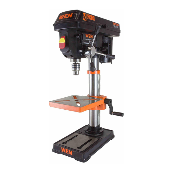
Assembly and adjustments……………………………………………………… Operation………………………………………………………………………... Maintenance…………………………………………………………………….. Exploded view…………………………………………………………………... Parts list………………………………………………………………………….. 27 Warranty………………………………………………………………………… Technical data 10" Drill Press with Laser Crosshair Item: 4210 Motor: 120 V, 60 Hz, 3.2 A Horsepower: 1/3 HP (single phase) Motor speed: 1700 RPM (no load) Drilling capacity: 2-1/4"... -
Page 3: General Safety Rules
General safety rules Safety is a combination of common sense, staying alert, and knowing how your drill press works. SAVE THESE SAFETY INSTRUCTIONS. WARNING: To avoid mistakes that could cause serious injury, do not plug in the drill press until the following steps have been read and understood. 1. - Page 4 General safety rules (continued) 13. NEVER LEAVE A RUNNING TOOL UNATTENDED. Turn the power switch to OFF. Do not leave the tool until it has come to a complete stop. 14. NEVER STAND ON A TOOL. Serious injury could result if the tool tips or is accidentally hit. DO NOT store anything above or near the tool.
-
Page 5: Specific Safety Rules For Drill Presses
Specific safety rules for drill presses WARNING: Do not operate your drill press until it is completely assembled and installed according to the instructions. 1. Never turn on the drill press before clearing the table of all objects (tools, scraps, etc.). 2. -
Page 6: Electrical Information
Electrical information Grounding instructions IN THE EVENT OF A MALFUNCTION OR BREAKDOWN, grounding provides the path of least resistance for electric current and reduces the risk of electric shock. This tool is equipped with an electric cord that has an equipment grounding conductor and a grounding plug. The plug MUST be plugged into a matching outlet that is properly installed and grounded in accordance with ALL local codes and ordinances. - Page 7 Electrical information (continued) WARNING: This drill press is for indoor use only. Do not expose to rain or use in damp locations. Guidelines for using extension cords Make sure your extension cord is in good condition. When using an extension cord, be sure to use one heavy enough to carry the current your product will draw.
-
Page 8: Know Your Drill Press
Know your drill press Power cord K Motor pulley U Light bulb(not provided) Tension lock knob L Motor V Quill Pulley housing cover M Feed handle W Depth scale On/off switch N Locking screw X Depth tension knob Light switch O Column Y Bevel scale Feed return spring and cover... -
Page 9: Assembly And Adjustments
Assembly and adjustments Unpacking (Fig. 2) Unpack the drill press and all its parts, and compare against the list below. Do not discard the carton or any packaging until the drill press is completely assembled. To protect the drill press from moisture, a protective coating has been applied to the machined surfaces. -
Page 10: Tools Needed For Assembly
Assembly and adjustments (continued) Tools needed for assembly • Adjustable wrench • Phillips® screwdriver • Hammer and block of wood Base to column (Fig. 3) 1. Set the base (1) on the floor. 2. Place the column tube (2) on the base (1), align the column support holes with the base holes. - Page 11 Assembly and adjustments (continued) 6. Place the collar (1) bevel side down over the rack. Tighten the set screw (2) with the 3 mm Allen wrench to hold the rack in position. Note: Make sure there is enough clearance to allow the table to rotate around the column.
- Page 12 Assembly and adjustments (continued) Feed handles (Fig. 9) 1. Thread the three feed handle rods (1) into the holes on the feed hub (2). 2. Hand tighten. Note: One or two of the feed handles may be removed if an unusually-shaped workpiece interferes with handle rotation.
- Page 13 Assembly and adjustments (continued) Mount the drill press (Fig. 12) Your drill press must be securely fastened through the mounting holes (1) to a stand or work bench with heavy-duty fasteners. This will prevent the drill press from tipping over, sliding, or walking during operation. IMPORTANT: If the stand or workbench has a tendency to move during operation, fasten it securely to the floor.
- Page 14 Assembly and adjustments (continued) Remove the chuck (Fig. 14) 1. Turn the feed handles (1) to lower the chuck (2) to the lowest position. 2. Place a ball joint separator (not shown) above the chuck (3) and tap it lightly with a hammer (4) to cause the chuck to drop from the spindle.
- Page 15 Assembly and adjustments (continued) Adjustments Align the belt pulleys (Fig. 16) 1. Check the alignment of the pulleys with a straight edge (1) (such as a ruler, level, or framing square) by laying the straight edge across the top of the pulleys (2). 2.
- Page 16 Assembly and adjustments (continued) WARNING: Disconnect the drill press from the power source before making any speed adjustments. Adjust speeds and tension the belt (Fig. 18) 1. Open the drill press pulley cover (1). 2. Loosen the belt tension knobs (2) on both sides of the drill press head.
- Page 17 Assembly and adjustments (continued) Tilt the table (Fig. 20) The table can be tilted from 0 to 45° to the left and right. 1. Loosen the bevel lock bolt (1) with a wrench. 2. Tilt the table (2) to the desired angle, using the bevel scale (3) as a basic guide.
- Page 18 Assembly and adjustments (continued) Drilling depth (Fig. 22) 1. To stop the drill at a specific depth for consistent and repetitive drilling, loosen the depth scale lock (1) located on the depth scale hub (2). 2. Turn the hub until the pointer (3) is aligned to the desired depth on the scale.
- Page 19 Assembly and adjustments (continued) Angular play of the spindle (Fig. 24) Move the spindle to the lowest downward position and hold in place. With your other hand, try to make it revolve around its axis with a side motion. If there is too much play proceed as follows: 1.
- Page 20 Assembly and adjustments (continued) WARNING: DO NOT STARE DIRECTLY AT THE LASER BEAM! A hazard may exist if you deliberately stare into the beam. Please observe all safety rules as follows: ♦ The laser shall be used and maintained in accordance with the manufacturer's instructions. ♦...
-
Page 21: Operation
Operation Switches (Fig. 28) To turn the drill press ON, insert the safety key (1) into the switch housing (2). As a safety feature, the switch cannot be turned ON without the key. Flip the switch upward to the ON position. To turn the drill press OFF, move the switch to the down position. - Page 22 Operation (continued) WARNING: To avoid injury, make sure the chuck key is removed from the chuck before starting any drilling operation. Drilling a hole Use a center punch or sharp nail to dent the workpiece where you want the hole. With the switch OFF, bring the drill bit down to the workpiece, lining it up with the location of the hole.
- Page 23 Operation (continued) Depth scale method (Fig. 31) 1. With the switch (1) OFF, turn the feed handle (2) until the drill bit tip (3) slightly touches the top of the workpiece (4). 2. Hold the feed handles in that position. 3.
- Page 24 Operation (continued) Drilling metal • Use metal-piercing twist drill bits. • It is always necessary to lubricate the tip of the drill with oil to prevent overheating the drill bit. • All metal workpieces should be clamped down securely. Any tilting, twisting, or shifting causes a rough drill hole, and increases the potential of drill bit breakage.
-
Page 25: Maintenance
Maintenance WARNING: For your own safety, turn the switch OFF and remove the plug from the power source before maintaining or lubricating the drill press. Blow out or vacuum sawdust or metal chips that accumulate in and on the motor, pulley housing, table, and work surface. -
Page 26: Exploded View
Exploded view... -
Page 27: Parts List
Parts list Stock # Description Stock # Description 4210-001 Column tube 4210-043 Lock washer 4210-002 Rack 4210-044 Screw 4210-003 Support column 4210-045 Pan cross screw 4210-004 Base 4210-046 Switch plate cover 4210-005 Hex head screw 4210-047 Rocker switch 4210-006 Crank handle... -
Page 28: Warranty
Limited Two Years Warranty WEN Products is committed to build tools that are dependable for years. Our warranties are consistent with this commitment and our dedication to quality. LIMITED WARRANTY OF WEN CONSUMER POWER TOOLS PRODUCTS FOR HOME USE GREAT LAKES TECHNOLOGIES, LLC ("Seller") warrants to the original purchaser only, that all WEN consumer power tools will be free from defects in material or workmanship for a period of two (2) years from date of purchase.
Need help?
Do you have a question about the 4210 and is the answer not in the manual?
Questions and answers