Advertisement
Table of Contents
- 1 Table of Contents
- 2 Technical Data
- 3 Safety Instructions
- 4 General Safety Rules
- 5 Specific Safety Rules for Drill Press
- 6 Grounding Instructions
- 7 Electrical Information
- 8 Know Your Drill Press
- 9 Assembly and Adjustments
- 10 Maintenance
- 11 Operation
- 12 Troubleshooting
- 13 Exploded View and Parts List
- 14 Warranty
- Download this manual
2015
Your new tool has been engineered and manufactured to WEN's highest standards for dependability,
ease of operation, and operator safety. When properly cared for, this product will supply you years
of rugged, trouble-free performance. Pay close attention to the rules for safe operation, warnings,
and cautions. If you use your tool properly and for intended purpose, you will enjoy years of safe,
reliable service.
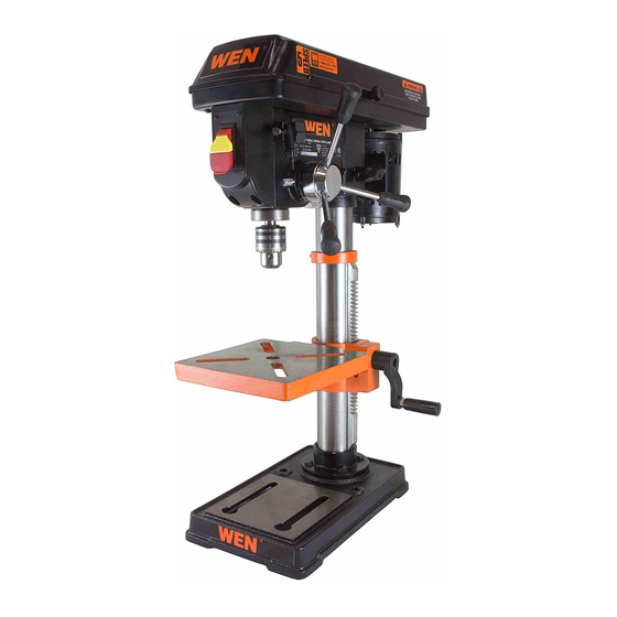
10˝ Drill Press with
Laser Crosshair
IMPORTANT:
NEED HELP? CONTACT US!
Have product questions? Need technical support?
Please feel free to contact us at:
800-232-1195
techsupport@wenproducts.com
WENPRODUCTS.COM
Model # 4210
bit.ly/wenvideo
(M-F 8AM-5PM CST)
Advertisement
Table of Contents

Related Manuals for Wen 4210


Summary of Contents for Wen 4210
- Page 1 IMPORTANT: Your new tool has been engineered and manufactured to WEN’s highest standards for dependability, ease of operation, and operator safety. When properly cared for, this product will supply you years of rugged, trouble-free performance. Pay close attention to the rules for safe operation, warnings, and cautions.
-
Page 2: Table Of Contents
TABLE OF CONTENTS Technical Data General Safety Rules Specific Safety Rules For Drill Press Electrical Information Know Your Drill Press Assembly and Adjustments Maintenance Operation Troubleshooting Exploded View and Parts List Warranty TECHNICAL DATA Motor: 120V, 60Hz, 375W, 3.2A Chuck Capacity: 1/2 inch Spindle Stroke: 2-1/2 inches... -
Page 3: General Safety Rules
GENERAL SAFETY RULES Safety is a combination of common sense, staying alert and knowing how your item works. SAVE THESE SAFETY INSTRUCTIONS. WARNING: To avoid mistakes and serious injury, do not plug in your tool until the following steps have been read and understood. 1. -
Page 4: Specific Safety Rules For Drill Press
GENERAL SAFETY RULES 14. NEVER STAND ON A TOOL. Serious injury could result if the tool tips or is accidentally hit. DO NOT store anything above or near the tool. 15. DO NOT OVERREACH. Keep proper footing and balance at all times. Wear oil-resistant rubber-soled foot- wear. -
Page 5: Electrical Information
SPECIFIC RULES FOR DRILL PRESS 10. Always stop the drill before removing scrap pieces from the table. 11. Use clamps or a vise to secure a workpiece to the table. This will prevent the workpiece from rotating with the drill bit. 12. - Page 6 ELECTRICAL INFORMATION GUIDELINES FOR USING EXTENSION CORDS Make sure your extension cord is in good condition. When using an extension cord, be sure to use one heavy enough to carry the current your product will draw. An undersized cord will cause a drop in line voltage resulting in loss of power and overheating.
-
Page 7: Know Your Drill Press
KNOW YOUR DRILL PRESS Electrical Cord Column Mount Motor Mount Base Housing Cover Table ON/OFF Switch Lightbulb Light ON/OFF Switch Spindle Spindle Return Spring Depth Adjustment Lock Chuck Depth Adjustment Guide Housing Knob Table Angle Guide Speed Chart Table Lock Front Spindle Rack Collar Drive (Motor) Spindle... -
Page 8: Assembly And Adjustments
ASSEMBLY AND ADJUSTMENTS UNPACKING Unpack the drill press and all of its parts. Compare against the list below. Do not discard the carton or any packaging until the drill press is completely assembled. To protect the drill press from moisture, a protective coating has been applied to the machine’s surfaces. Remove this coating with a soft cloth moistened with kerosene or WD-40®. - Page 9 ASSEMBLY AND ADJUSTMENTS ATTACHING COLUMN ASSEMBLY TO BASE 1. Place the column tube on the base, aligning the column support holes to the base holes. 2. Install a hex head bolt in each column support hole and tighten bolts using the adjustable wrench.
- Page 10 ASSEMBLY AND ADJUSTMENTS DRILL PRESS HEAD TO COLUMN CAUTION: The drill press head is heavy. To avoid in- jury, two people should lift it into position. 1. Carefully lift the drill press head assembly and position it over the column (Fig.
- Page 11 ASSEMBLY AND ADJUSTMENTS MOUNT THE DRILL PRESS (Fig. H) The drill press must be securely fastened through the mounting holes to a stand or workbench with heavy-duty fasteners (Fig. H). This will pre- vent the drill press from tipping over, sliding, or walking during opera- tion.
- Page 12 ASSEMBLY AND ADJUSTMENTS INSTALLING LASER BATTERIES (PRE-INSTALLED) 1. Turn off the drill laser. 2. Pull the tab located below the laser switch and lift up the laser switch cover. (Fig. K) 3. Install two AAA batteries into the battery slots and close the switch cover.
- Page 13 ASSEMBLY AND ADJUSTMENTS TILT THE TABLE 1. Loosen the hex lock bolt with a suitable socket wrench (located under the table, as shown in Fig. N). 2. Tilt the table to the desired angle, using the bevel scale (Fig. O) as a basic guide.
- Page 14 2. Lock the Scale Ring in Place by tightening the depth knob. SPEED ADJUSTMENT For a video demonstration using the WEN 8-Inch Drill Press, visit http://bit.ly/1LGcLIb 1. To change to another one of the five available speeds, open the belt housing and loosen the belt tension locking knob found cirled in Fig.
- Page 15 ASSEMBLY AND ADJUSTMENTS ADJUSTING THE LASER (Fig. S) WARNING: Do not stare directly at the laser beam. Please observe all safety rules. • Never aim the beam at a person or an object other than the workpiece. • Do not project the laser beam into the eyes of others. •...
-
Page 16: Maintenance
ASSEMBLY AND ADJUSTMENTS REPLACING THE BELT WARNING: Disconnect the drill press from the power source before replacing the belt. Belt tension and drill press speed is controlled by automatic adjustments made to the diameter of the front spindle when the drive handle is moved. 1. -
Page 17: Operation
OPERATION DRILL PRESS ON/OFF SWITCH (Fig. U) 1. To turn the drill press ON, insert the yellow safety key (1) into the switch housing (2). As a safety feature, the switch cannot be turned ON without the safety key. 2. Flip the switch upward to the ON position. Fig. - Page 18 OPERATION DRILLING SPEEDS There are a few important factors to keep in mind when determining the best drilling speed: • Material type • Hole size • Drill bit or cutter type • Quality desired Smaller drill bits require greater speed than larger drill bits. Softer materials require greater speed than harder materials.
-
Page 19: Troubleshooting
TROUBLESHOOTING PROBLEM CAUSES SOLUTIONS Noisy operation 1) Incorrect belt tension 1) Adjust the belt tension (See REPLACE THE 2) Dry spindle BELT section) 3) Loose spindle pulley 2) Lubricate the spindle 4) Loose motor pulley 3) Tighten the retaining nut on the pulley insert 4) Tighten the set screw on the side of the mo- tor pulley The drill bit burns or... -
Page 20: Exploded View And Parts List
EXPLODED VIEW & PARTS LIST... - Page 21 Part # Description Qty Part # Description 4210B-001 V-belt 1 4210B-055 Connecting Terminal 4210B-002 Motor Pulley 1 4210B-056 Knob 4210B-003 Set Screw 2 4210B-057 Feeding Handle 4210B-004 Power Cord 1 4210B-058 Gear Shaft 4210B-005 Spindle Pulley 1 4210B-059 Laser 4210B-006 Set Screw 2 4210B-060 Set Screw 4210B-007 Belt House Knob 1 4210B-061 Rivet...
-
Page 22: Warranty
LIMITED TWO YEAR WARRANTY WEN Products is committed to building tools that are dependable for years. Our warranties are consistent with this commitment and our dedication to quality. LIMITED WARRANTY OF WEN CONSUMER POWER TOOLS PRODUCTS FOR HOME USE GREAT LAKES TECHNOLOGIES, LLC (“Seller”) warrants to the original purchaser only, that all WEN con- sumer power tools will be free from defects in material or workmanship for a period of two (2) years from date of purchase.
Need help?
Do you have a question about the 4210 and is the answer not in the manual?
Questions and answers