Table of Contents
Advertisement
Your new tool has been engineered and manufactured to WEN's highest standards for dependability,
ease of operation, and operator safety. When properly cared for, this product will supply you years
of rugged, trouble-free performance. Pay close attention to the rules for safe operation, warnings,
and cautions. If you use your tool properly and for intended purpose, you will enjoy years of safe,
reliable service.
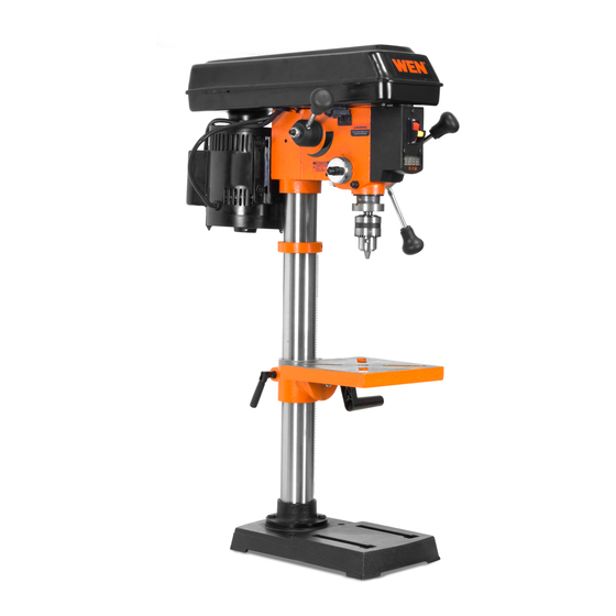
10˝ VARIABLE SPEED
IMPORTANT:
NEED HELP? CONTACT US!
Have product questions? Need technical support?
Please feel free to contact us at:
800-232-1195
techsupport@wenproducts.com
WENPRODUCTS.COM
DRILL PRESS
(M-F 8AM-5PM CST)
Model # 4212
bit.ly/wenvideo
Advertisement
Table of Contents

Related Manuals for Wen 4212


Summary of Contents for Wen 4212
-
Page 1: Drill Press
IMPORTANT: Your new tool has been engineered and manufactured to WEN’s highest standards for dependability, ease of operation, and operator safety. When properly cared for, this product will supply you years of rugged, trouble-free performance. Pay close attention to the rules for safe operation, warnings, and cautions. -
Page 2: Table Of Contents
Know Your Drill Press Assembly and Adjustments Operation Maintenance Troubleshooting Exploded View and Parts List Warranty TECHNICAL DATA 4212 Model Number: 120 V, 60 Hz, 4.5 A, 3/4 HP Motor: 530-3100 RPM (no load) Speed: 1/16 in. to 1/2 in. Chuck Capacity:... -
Page 3: General Safety Rules
GENERAL SAFETY RULES Safety is a combination of common sense, staying alert and knowing how your item works. SAVE THESE SAFE- TY INSTRUCTIONS. WARNING: To avoid mistakes and serious injury, do not plug in your tool until the following steps have been read and understood. 1. -
Page 4: Specific Safety Rules For Drill Press
GENERAL SAFETY RULES 15. DO NOT OVERREACH. Keep proper footing and balance at all times. Wear oil-resistant rubber-soled foot- wear. Keep the floor clear of oil, scrap, and other debris. 16. MAINTAIN TOOLS PROPERLY. ALWAYS keep tools clean and in good working order. Follow instruc- tions for lubricating and changing accessories. -
Page 5: Electrical Information
SPECIFIC RULES FOR DRILL PRESS 10. Always stop the drill before removing scrap pieces from the table. 11. Use clamps or a vise to secure a workpiece to the table. This will prevent the workpiece from rotating with the drill bit. 12. -
Page 6: Know Your Drill Press
ELECTRICAL INFORMATION GUIDELINES FOR USING EXTENSION CORDS Make sure your extension cord is in good condition. When using an extension cord, be sure to use one heavy enough to carry the current your product will draw. An undersized cord will cause a drop in line voltage resulting in loss of power and overheating. -
Page 7: Assembly And Adjustments
ASSEMBLY AND ADJUSTMENTS UNPACKING Unpack the drill press and all of its parts. Compare against the list below. Do not discard the carton or any packaging until the drill press is completely assembled. To protect the drill press from moisture, a protective coating has been applied to the machine’s surfaces. Remove this coating with a soft cloth moistened with kerosene or WD-40®. -
Page 8: Table To Column
ASSEMBLY AND ADJUSTMENTS COLUMN ASSEMBLY TO BASE 1. Place the column tube (Fig. A - 2) on the base (Fig. A - 1), aligning the column support holes to the base holes. 2. Install a hex head bolt (Fig. A - 3) in each column support hole and tighten bolts using the adjustable wrench. - Page 9 ASSEMBLY AND ADJUSTMENTS DRILL PRESS HEAD TO COLUMN CAUTION: The drill press head is heavy. To avoid injury, two people should lift it into position. 1. Carefully lift the drill press head assembly and position it over the column (Fig. D). 2.
- Page 10 ASSEMBLY AND ADJUSTMENTS MOUNT THE DRILL PRESS The drill press must be securely fastened through the mounting holes (Fig. J - 1, Fig. K) to a stand or workbench with heavy-duty fasteners. This will pre- vent the drill press from tipping over, sliding, or walking during operation. IMPORTANT: If the stand or workbench has a tendency to move during operation, fasten the workbench securely to the floor.
- Page 11 ASSEMBLY AND ADJUSTMENTS RAISE OR LOWER THE TABLE 1. Loosen the support lock handle (Fig. N - 2) and turn the crank handle (Fig. N - 1) until the table is at the desired height. 2. Tighten the support lock handle (Fig. N - 2) before drilling. ROTATE THE TABLE 1.
- Page 12 ASSEMBLY AND ADJUSTMENTS WARNING: To avoid injury, make sure the chuck key is removed from the chuck before starting any drilling operation. INSTALLING A DRILL BIT 1. Place the chuck key into the side keyhole of the chuck, meshing the key with the gear teeth.
- Page 13 ASSEMBLY AND ADJUSTMENTS ADJUSTING THE LASER WARNING: Do not stare directly at the laser beam. Please observe all safety rules. • Never aim the beam at a person or an object other than the workpiece. • Do not project the laser beam into the eyes of others. •...
-
Page 14: Operation
ASSEMBLY AND ADJUSTMENTS ANGULAR “PLAY” OF THE SPINDLE Move the spindle to the lowest downward position and hold in place. Try to make the spindle revolve around its axis while also moving it with a side motion. If there is too much “play”, proceed as follows: 1. - Page 15 OPERATION INSTALLING A DRILL BIT 1. With the switch OFF, open the chuck jaws (Fig. X - 1) using the chuck key (Fig. X - 2). Turn the chuck key counterclockwise to open the jaws. 2. Insert the drill bit (Fig. X - 3) into the chuck far enough to obtain the maxi- mum gripping by the jaws, but not far enough to touch the spiral grooves of the drill bit when the jaws are tightened.
- Page 16 For small workpieces that cannot be clamped to the table, use a drill press vise. The vise must be clamped or bolted to the table (Fig. Z). Compatible WEN Drill Press Vises include our WEN 424DPV 4-Inch Drill Press Vise and our WEN 423DPV 3-Inch Drill Press Vise.
-
Page 17: Maintenance
OPERATION FEEDING THE DRILL BIT • Pull down on the feed handles with only enough force to allow the drill bit to cut. • Feeding too rapidly might stall the motor, cause the belt to slip, damage the workpiece, or break the drill bit. •... -
Page 18: Troubleshooting
TROUBLESHOOTING PROBLEM CAUSES SOLUTIONS Noisy operation 1) Incorrect belt tension 1) Adjust the belt tension 2) Dry spindle 2) Lubricate the spindle 3) Loose spindle pulley 3) Tighten the retaining nut on the pulley insert 4) Loose motor pulley 4) Tighten the set screw on the side of the mo- tor pulley The drill bit burns or 1) Drilling at the incorrect speed... -
Page 19: Exploded View And Parts List
EXPLODED VIEW & PARTS LIST... -
Page 20: Motor
EXPLODED VIEW & PARTS LIST Part Number Description Part Number Description Part Number Description 4212C-001 V belt 4212C-045 Cord clamp 4212C-089 Lock washer 4212C-002 Set screw 4212C-046 Hex nut 4212C-090 Pan head screw 4212C-003 Retaining ring 4212C-047 Lock nut 4212C-091 Transformer 4212C-004 Upper motor pulley... - Page 21 LIMITED TWO YEAR WARRANTY WEN Products is committed to building tools that are dependable for years. Our warranties are consistent with this commitment and our dedication to quality. LIMITED WARRANTY OF WEN CONSUMER POWER TOOLS PRODUCTS FOR HOME USE GREAT LAKES TECHNOLOGIES, LLC (“Seller”) warrants to the original purchaser only, that all WEN con- sumer power tools will be free from defects in material or workmanship for a period of two (2) years from date of purchase.
- Page 22 Thanks for remembering...
Need help?
Do you have a question about the 4212 and is the answer not in the manual?
Questions and answers