WEN JT630H, JT833H - 10-Amp 8-Inch Spiral Benchtop Jointer Manual
- Instruction manual (28 pages)
Advertisement
- 1 INTRODUCTION
- 2 SPECIFICATIONS
- 3 GENERAL SAFETY RULES
- 4 JOINTER SAFETY WARNINGS
- 5 ELECTRICAL INFORMATION
- 6 UNPACKING & PACKING LIST
- 7 KNOW YOUR JOINTER
- 8 ASSEMBLY & ADJUSTMENTS
- 9 OPERATION
- 10 BEVEL AND CHAMFER
- 11 ATTACH A VACUUM HOSE
- 12 ON/OFF SWITCH
- 13 MAINTENANCE
- 14 TROUBLESHOOTING GUIDE
- 15 Documents / Resources
INTRODUCTION
Thanks for purchasing the WEN Benchtop Jointer. We know you are excited to put your tool to work, but first, please take a moment to read through the manual. Safe operation of this tool requires that you read and understand this operator's manual and all the labels affixed to the tool. This manual provides information regarding potential safety concerns, as well as helpful assembly and operating instructions for your tool.
Indicates danger, warning, or caution. The safety symbols and the explanations with them deserve your careful attention and understanding. Always follow the safety precautions to reduce the risk of fire, electric shock or personal injury. However, please note that these instructions and warnings are not substitutes for proper accident prevention measures.
NOTE: The following safety information is not meant to cover all possible conditions and situations that may occur. WEN reserves the right to change this product and specifications at any time without prior notice.
At WEN, we are continuously improving our products. If you find that your tool does not exactly match this manual, please visit wenproducts.com for the most up-to-date manual or contact our customer service at 1-800-232-1195.
Keep this manual available to all users during the entire life of the tool and review it frequently to maximize safety for both yourself and others.
SPECIFICATIONS
| Model Number | JT630H | JT833H |
| Motor | 120V, 60 Hz, 10A | 120V, 60 Hz, 10A |
| Cutterhead Rotation Speed | 11,000 RPM | 11,000 RPM |
| Max Cutting Width | 6 Inches | 8 Inches |
| Max Cutting Depth | 1/8 Inch | 1/8 Inch* |
| Recommended Cutting Depth | 1/32 Inch | 1/32 Inch |
| Number of Blades | 12 | 16 |
| Table Size | 30 in. x 6-3/16 in. | 33 in. x 8 in. (extensions up to 51 in.) |
| Fence Size | 4-1/4 in. x 19-3/4 in. | 4-1/4 in. x 19-3/4 in. |
| Dust Port Diameter | 2-1/2 Inches | 2-1/2, 4 Inches |
| Fence Bevel | 90-135° | 90-135° |
| Product Dimensions | 30 in. x 17.5 in. x 12.5 in. | 34.5 in. x 18.75 in. x 12.5 in. |
| Weight | 36.8 lbs | 55.1 lbs |
*When jointing boards over 6 inches, reduce maximum cutting depth by 1/32 inch per inch
GENERAL SAFETY RULES

Read all safety warnings and all instructions. Failure to follow the warnings and instructions may result in electric shock, fire and/or serious injury.
Safety is a combination of common sense, staying alert and knowing how your item works. The term "power tool" in the warnings refers to your mains-operated (corded) power tool or battery-operated (cordless) power tool.
SAVE THESE SAFETY INSTRUCTIONS.
WORK AREA SAFETY
- Keep work area clean and well lit. Cluttered or dark areas invite accidents.
- Do not operate power tools in explosive atmospheres, such as in the presence of flammable liquids, gases or dust. Power tools create sparks which may ignite the dust or fumes.
- Keep children and bystanders away while operating a power tool. Distractions can cause you to lose control.
ELECTRICAL SAFETY
- Power tool plugs must match the outlet. Never modify the plug in any way. Do not use any adapter plugs with earthed (grounded) power tools. Unmodified plugs and matching outlets will reduce risk of electric shock.
- Avoid body contact with earthed or grounded surfaces such as pipes, radiators, ranges and refrigerators. There is an increased risk of electric shock if your body is earthed or grounded.
- Do not expose power tools to rain or wet conditions. Water entering a power tool will increase the risk of electric shock.
- Do not abuse the cord. Never use the cord for carrying, pulling or unplugging the power tool. Keep cord away from heat, oil, sharp edges or moving parts. Damaged or entangled cords increase the risk of electric shock.
- When operating a power tool outdoors, use an extension cord suitable for outdoor use. Use of a cord suitable for outdoor use reduces the risk of electric shock.
- If operating a power tool in a damp location is unavoidable, use a ground fault circuit interrupter (GFCI) protected supply. Use of a GFCI reduces the risk of electric shock.
PERSONAL SAFETY
- Stay alert, watch what you are doing and use common sense when operating a power tool. Do not use a power tool while you are tired or under the influence of drugs, alcohol or medication. A moment of inattention while operating power tools may result in serious personal injury.
- Use personal protective equipment. Always wear eye protection. Protective equipment such as a respiratory mask, non-skid safety shoes and hearing protection used for appropriate conditions will reduce the risk of personal injury.
- Prevent unintentional starting. Ensure the switch is in the off-position before connecting to power source and/or battery pack, picking up or carrying the tool. Carrying power tools with your finger on the switch or energizing power tools that have the switch on invites accidents.
- Remove any adjusting key or wrench before turning the power tool on. A wrench or a key left attached to a rotating part of the power tool may result in personal injury.
- Do not overreach. Keep proper footing and balance at all times. This enables better control of the power tool in unexpected situations.
- Dress properly. Do not wear loose clothing or jewelry. Keep your hair and clothing away from moving parts. Loose clothes, jewelry or long hair can be caught in moving parts.
- If devices are provided for the connection of dust extraction and collection facilities, ensure these are connected and properly used. Use of dust collection can reduce dust-related hazards.
POWER TOOL USE AND CARE
- Do not force the power tool. Use the correct power tool for your application. The correct power tool will do the job better and safer at the rate for which it was designed.
- Do not use the power tool if the switch does not turn it on and off. Any power tool that cannot be controlled with the switch is dangerous and must be repaired.
- Disconnect the plug from the power source and/or the battery pack from the power tool before making any adjustments, changing accessories, or storing power tools. Such preventive safety measures reduce the risk of starting the power tool accidentally.
- Store idle power tools out of the reach of children and do not allow persons unfamiliar with the power tool or these instructions to operate the power tool. Power tools are dangerous in the hands of untrained users.
- Maintain power tools. Check for misalignment or binding of moving parts, breakage of parts and any other condition that may affect the power tool's operation. If damaged, have the power tool repaired before use. Many accidents are caused by poorly maintained power tools.
- Keep cutting tools sharp and clean. Properly maintained cutting tools with sharp cutting edges are less likely to bind and are easier to control.
- Use the power tool, accessories and tool bits, etc. in accordance with these instructions, taking into account the working conditions and the work to be performed. Use of the power tool for operations different from those intended could result in a hazardous situation.
- Use clamps to secure your workpiece to a stable surface. Holding a workpiece by hand or using your body to support it may lead to loss of control.
- KEEP GUARDS IN PLACE and in working order.
SERVICE
- Have your power tool serviced by a qualified repair person using only identical replacement parts. This will ensure that the safety of the power tool is maintained.
CALIFORNIA PROPOSITION 65 WARNING
Some dust created by power sanding, sawing, grinding, drilling, and other construction activities may contain chemicals, including lead, known to the State of California to cause cancer, birth defects, or other reproductive harm. Wash hands after handling. Some examples of these chemicals are:
- Lead from lead-based paints.
- Crystalline silica from bricks, cement, and other masonry products.
- Arsenic and chromium from chemically treated lumber.
Your risk from these exposures varies depending on how often you do this type of work. To reduce your exposure to these chemicals, work in a well-ventilated area with approved safety equipment such as dust masks specially designed to filter out microscopic particles.
JOINTER SAFETY WARNINGS
Do not let comfort or familiarity with the product replace strict adherence to product safety rules. Failure to follow the safety instructions may result in serious personal injury.
JOINTER SAFETY
- TOOL PURPOSE
This jointer is designed for creating flat surfaces on wood or wood-like products only. Smoothing other materials could result in fire, injury, or damage to the workpiece. Using the machine for any other purpose for which it is not designed may result in serious injuries, machine damage and voiding of the warranty. - MACHINE MOUNTING
For the operator's safety, the jointer must be securely mounted onto a flat and stable surface or stand. - PERSONAL SAFETY
- Always wear ANSI Z87.1-approved glasses with side shields, hearing protection, and a dust mask.
- Do not wear loose clothing or jewelry, as they might get drawn in by the tool. Tie back long hair.
- DO NOT wear gloves while operating this machine.
- ELECTRIC CORDS
Keep cords away from heat, oil, sharp edges, and moving parts of the tool. Have an electrician replace or repair damaged or worn cords immediately. - TOOL & ACCESSORIES INSPECTION
Before operation, check the tool and accessories for any damage or missing parts. Do not use the tool if any part is missing or damaged. Make sure all adjustments are correct and all connections are tight. Keep all guards in place. Make sure all moving parts are free from interference. - JOINTER ACCESSORIES
- Do not use blades, or any accessories that are damaged or worn. Replace blades as they become damaged or dull.
- Make sure all blades and accessories are sharp enough for the task at hand before using them.
- Make sure blades are aligned and properly attached to the cutterhead before using your planer.
- Always turn off and unplug the unit before doing any cleaning or maintenance. Use a brush or compressed air to remove chips or debris. Never use your hands to remove excess material and debris.
- Allow the jointer to come to full speed before using the machine.
- WORKPIECE REQUIREMENTS
Check the workpiece carefully for splits, knots, nails, or other obstructions. These types of blemishes may cause a safety risk during smoothing. - USE HIGH QUALITY LUMBER
Blades last longer and cuts are smoother with higher quality wood. - DO NOT joint material shorter than 8-1/8", narrower than 3/4", or thinner than 1/4". Never make a jointing cut deeper than 1/8". Use a push block or push stick for jointing material narrower or thinner than 3".
- PREVENTING ACCIDENTAL STARTING
Make sure the power switch is in the OFF position prior to plugging in the machine. Always make sure the power switch is in the OFF position and the machine is unplugged when doing any cleaning, assembly, setup operations, or when not in use. - SUPPORT THE WORKPIECE adequately at all times during operation; maintain control of the workpiece.
- DO NOT back workpiece toward the infeed table.
- If gluing a workpiece, always use a high quality glue that meets the needs of the particular workpiece.
- Take precautions against KICKBACK. DO NOT permit anyone to stand or cross in line of the cutterhead's rotation. Kickback or thrown debris will travel in this direction.
- Do not operate this tool until it is completely assembled and installed according to the instructions.
- Remove scrap pieces and other objects from the table and work area before turning ON the jointer.
- Do not touch moving pieces. Keep hands away from all moving parts and cutting surfaces.
- Never perform layout, assembly or set-up work on the table while the jointer is operating.
- Always turn off and unplug the machine before cleaning, making adjustments or changing attachments. Accidental start-ups may occur if the tool is plugged in during an accessory change or adjustment.
- CLEANING
Never use solvents to clean plastic parts. Solvents could dissolve or otherwise damage the material.
Use only a soft damp cloth to clean plastic parts. - REPLACEMENTS
Should any component of your jointer be missing/ damaged or fail in any way, shut off the switch and remove the plug from power supply outlet. Replace the missing, damaged, or failed parts using only identical replacement parts before resuming operation.
These safety instructions can't possibly warn of every scenario that may arise with this tool, always make sure to stay alert and use common sense during operation.
ELECTRICAL INFORMATION
GROUNDING INSTRUCTIONS
In the event of a malfunction or breakdown, grounding provides the path of least resistance for an electric current and reduces the risk of electric shock. This tool is equipped with an electric cord that has an equipment grounding conductor and a grounding plug. The plug MUST be plugged into a matching outlet that is properly installed and grounded in accordance with ALL local codes and ordinances.
- Do not modify the plug provided. If it will not fit the outlet, have the proper outlet installed by a licensed electrician.
- Improper connection of the equipment grounding conductor can result in electric shock. The conductor with the green insulation (with or without yellow stripes) is the equipment grounding conductor. If repair or replacement of the electric cord or plug is necessary, DO NOT connect the equipment grounding conductor to a live terminal.
- Check with a licensed electrician or service personnel if you do not completely understand the grounding instructions or whether the tool is properly grounded.
- Use only three-wire extension cords that have three-pronged plugs and outlets that accept the tool's plug. Repair or replace a damaged or worn cord immediately.
![]()


In all cases, make certain the outlet in question is properly grounded. If you are not sure, have a licensed electrician check the outlet.
GUIDELINES AND RECOMMENDATIONS FOR EXTENSION CORDS
When using an extension cord, be sure to use one heavy enough to carry the current your product will draw. An undersized cord will cause a drop in line voltage resulting in loss of power and overheating. The table below shows the correct size to be used according to cord length and ampere rating. When in doubt, use a heavier cord. The smaller the gauge number, the heavier the cord.
| AMPERAGE | REQUIRED GAUGE FOR EXTENSION CORDS | |||
| 25 ft. | 50 ft. | 100 ft. | 150 ft. | |
| 10A | 14 gauge | 12 gauge | 10 gauge | 8 gauge |
- Examine extension cord before use. Make sure your extension cord is properly wired and in good condition. Always replace a damaged extension cord or have it repaired by a qualified person before using it.
- Do not abuse extension cord. Do not pull on cord to disconnect from receptacle; always disconnect by pulling on plug. Disconnect the extension cord from the receptacle before disconnecting the product from the extension cord. Protect your extension cords from sharp objects, excessive heat and damp/wet areas.
- Use a separate electrical circuit for your tool. This circuit must not be less than a 12-gauge wire and should be protected with a 15A time-delayed fuse. Before connecting the motor to the power line, make sure the switch is in the OFF position and the electric current is rated the same as the current stamped on the motor nameplate. Running at a lower voltage will damage the motor.
UNPACKING & PACKING LIST
UNPACKING
With the help of a friend or trustworthy foe, such as one of your in-laws, carefully remove the jointer from the packaging and place it on a sturdy, flat surface. Make sure to take out all contents and accessories. Do not discard the packaging until everything is removed. Check the packing list below to make sure you have all of the parts and accessories. If any part is missing or broken, please contact customer service at 1-800-232-1195 (M-F 8-5 CST), or email techsupport@wenproducts.com.
PACKING LIST

* Only JT833H; Not included with JT630H
** Pre-installed on JT833H
JT630H & JT833H HARDWARE BAG
- Fence Sliding Handle (1)
- M6x16 Socket Head Screw (2)
- Square Nut (2)
- Washer (1)
- 2.5mm Hex Wrench (1)
- 4mm Hex Wrench (1)
- Star Wrench (1)
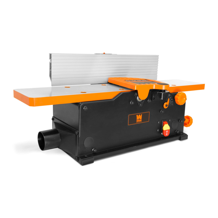
KNOW YOUR JOINTER
TOOL PURPOSE
Resurface boards, flatten workpieces, and much more with your WEN Jointer. Refer to the diagram below to become familiarized with the parts and controls of your jointer.
JT630H

JT833H

NOTE: A protective coating of lubricating oil has been applied during assembly to protect against rust. Wipe down all components thoroughly. Apply a light coat of good-quality paste wax to the table and fence to protect the surfaces and make boards slide smoothly.
ASSEMBLY & ADJUSTMENTS
ATTACH THE FENCE
- Attach the fence support bracket (Fig. 2 - 1) to the jointer with four socket head bolts (Fig. 2 - 2)

- Assemble the fence sliding bracket (Fig. 3 - 1) to the fence (Fig. 3 - 2). Insert the two socket head bolts (Fig. 3 - 3) through the top of the fence sliding bracket and screw the square nuts (Fig. 3 - 4) onto the bolts but do not tighten.

- Slide the square nuts into the grooves on the back of the fence and position the fence sliding bracket to the middle of the fence. Tighten the socket head screws (Fig. 3 - 3) once the sliding fence bracket is correctly positioned.
NOTE: Use the fence cutout (Fig 4 - 1) to position the fence sliding bracket in the center of the fence.

- Place the upper fence assembly (Fig. 4 - 2) on top of the fence support bracket. Insert the sliding handle (Fig. 4 - 3) through the flat washer (Fig. 4 - 4), through the sliding bracket, and then though the support bracket.
- Hold the rectangular nut under the fence support bracket so that it fits snuggly into the groove with the flat side up. Thread the sliding handle through the nut until it is tight. and the fence is secured.


NOTE: The fence sliding handle and fence bevel handle are spring-loaded and can be re-positioned as need be. Pull out on the handle, re-position it, and let it spring back in place.
NOTE: The stop limits on the fence bracket have been set at the factory, but should be checked with an angle gauge to measure exactly 90° and 135° between the fence and the table top at each stop limit, respectively. The stop limits can be modified by tightening or loosening the set screws if the angles are not precise.
INSTALL THE DUST CHUTE
- Remove the two M6x12 screws (Fig. 5 - 1) from the body of the jointer and the two self tapping screws (Fig. 5 - 2) from the feet of the jointer.

- Position the dust port (Fig. 5 - 3) and reinstall all four screws. Be sure not to over-tighten the screws as doing so might damage the dust port.
NOTE: JT833H comes with an optional dust port adapter to allow you to connect to 2-1/2" or 4" hoses.

ADJUST THE TABLE SUPPORTS
The 8" jointer, JT833H, is equipped with a extendable table supports (Fig. 6 - 1). To extend the supports, loosen the two knobs (Fig. 6 - 2) on each side of the support bar and reposition the support to the desired position. Once the support is in the desired position, re-tighten the knobs underneath the table.

ADJUST AND LEVEL THE TABLE
The infeed and outfeed table have been pre-set at the factory to be level and in line with the blades. However, if shipping or use has caused the table to shift out of level, adjust the tables with the following steps. Make sure that the unit is unplugged from any power supply before adjusting the table.
NOTE: This procedure involves close proximity to the helical blades. To avoid cuts, wear cut-proof or cut-resistant gloves when performing maintenance work. Remove the gloves before operating the jointer.
- Set the depth of cut scale (Fig. 7 - 1) to "0" to bring the infeed table to its most up most position.

- Rotate the cutterhead such that some of the blades are at their highest point. The cutterhead can be safety rotated using the included 4 mm hex wrench at the front end of the cutterhead under the blade guard flange (Fig. 7 - 2).
- Use a long metal straight edge to check the height of the outfeed table. Place the straight edge over the outfeed table and the cutterhead blades. Check that the blades barely touch the straight edge at both the front and back of the cutterhead. You will need to rotate the cutterhead to check both the front and back alignment of the table.
- If the blades do not touch the straight edge or drastically hit the straight edge, the outfeed table will need to be adjusted.
- Use the included 4 mm hex wrench to loosen and remove the bolt (Fig. 8 - 1) countersunk in the table. Remove the washer as well to access the slotted (Fig. 8 - 2) screw underneath.

- .Use a flat head screwdriver to adjust the slotted screw. Turning the screw clockwise will lift the table up and turning counterclockwise will lower the table. Adjustments to the screw should be minimal, with only a 1/20th turn before rechecking the table's position with the straight edge.
- Once the table is level and at the correct height, reinstall the washer and bolt to secure the table.
- Use the included 4 mm hex wrench to loosen and remove the bolt (Fig. 8 - 1) countersunk in the table. Remove the washer as well to access the slotted (Fig. 8 - 2) screw underneath.
- Once the outfeed table is set at the correct height, follow the steps above to ensure that the infeed table is at the correct height.
- When both the infeed and outfeed tables are aligned with the blades, lay the straightedge across the infeed and outfeed tables to ensure that they are level. If the tables are not perfectly aligned, tune the outfeed table to the infeed table using step 4 above to adjust the level of the table.


Do not plug in or turn on the tool until it is fully assembled according to these instructions. Failure to follow the safety instructions may result in serious personal injury.
ADJUST THE DEPTH OF CUT
The depth of cut is adjusted by the relative positioning of the infeed table with respect to the cutterhead. The infeed table (Fig. 9 - 1) can be raised or lowered using the infeed adjustment knob (Fig. 9 - 2). Turning the knob counterclockwise will raise the infeed table, causing less wood to be removed from the workpiece, as seen on the depth of cut scale (Fig. 9 - 3). Turning the hand wheel clockwise will lower the infeed table, causing more wood to be removed from the workpiece. Always make sure that the front lock knob (Fig. 9 - 4) is loosened before changing the depth of cut and tightened after the desired change has been made so that the depth of cut does not differ between cuts. Do not make jointing cuts deeper than 1/8 of an inch.

NOTE: For a smooth finish, it is recommended to do multiple passes at a lower depth. We recommend using a depth of 1/32". Always using a depth of 1/8" will shorten the lifespan of your jointer and give you a rougher finish.
BEVEL THE FENCE
NOTE: The fence can easily be set to 0° and 45° using the limit stops (Fig. 10 - 2) on the fence. However, it is always advisable to check the angles with a piece of scrap wood before jointing your final workpiece. Adjust the set screws that act as limit stops if they are not exact or have moved from shipping or use.
The fence can be positioned to joint the wood at any angle from 0° to 45°.
- Before adjusting the fence's angle, make sure that the unit is unplugged and the power switch is in the OFF position.
- Turn the fence bevel handle counterclockwise to loosen it. If you find it necessary to reposition the handle in order to loosen it, pull it outwards, turn the handle to the new position, and release it.
- Manually tilt the fence to desired angle; use an angle gauge block (not included) to see the current angle.
- Once the desired angle has been achieved, tighten the bevel handle.
MOVE THE FENCE
- Before adjusting the fence's position, make sure that the unit is unplugged and the power switch is in the OFF position.
- Loosen the fence sliding handle (Fig. 10 - 1).

- Slide the fence to the desired position. The fence can be positioned over the blade so that only the desired width of the blade is exposed. Make sure the exposed width matches that of the workpiece.
- Tighten the fence sliding handle so that the fence is secure.

AVOID DAMAGE TO BLADES
Jointers are a precision woodworking machine and should be used on quality lumber only. Do not join dirty boards; dirt and small stones are abrasive and will wear out the blades.
For proper operation, attach a dust collection system to the dust port, on the left of the jointer. Attaching a dust collection system is very important when taking deeper cuts to prevent wood chips clogging the unit.
Remove nails and staples. Only use the jointer to cut wood. Avoid knots. Heavily cross-grained wood makes knots hard. Knots can come loose and jam blades.
Assess the value of badly warped boards. You may be tempted to take a deep cut to square the boards quickly, when a better approach is to use several passes with a shallower cut.
OPERATION
FEED A WORKPIECE
Feed rate refers to the rate at which wood is passed over the blades. An even feed rate produces a uniform finish.
- Hold the work piece firmly down on the feed table and against the fence.
- Feed the work piece at an even rate over the cutterhead. Any hesitation or stopping will cause a "step" to be cut in the work piece. See Figs. 11 - 13 for different feeding methods.

- As your trailing hand passes over the cutterhead, remove your leading hand and place behind your trailing hand and repeat until the entire length of the workpiece has been cut. Use a push block (Fig. 13 - 1) to hold and feed the workpiece when jointing wood that is narrower than 3 inches or thinner than 3 inches.
- Cut with the grain whenever possible (Fig. 14). Do not feed against the end grain (Fig. 15), otherwise the workpiece may split and shatter. If the nature of the workpiece requires you to joint against the grain, take extremely light cuts and feed slowly. When using long work pieces, use extra supports at both ends of the jointer.
![]()


BEVEL AND CHAMFER
The fence on the jointer is adjustable from 0° to 45°. Adjust the fence to the desired angle and tighten the bevel handle.
Beveling refers to cutting the entire edge of a board at an angle. Beveling may require several passes due to the depth of the cut needed. See Fig. 16.
Chamfering refers to removing only the corner of the edge of a board. Normally a chamfer is made in one pass; so a 1/16-inch deep cut is made. See Fig. 16.

ATTACH A VACUUM HOSE
A 2-1/2" (or 4" with the dust port adapter on JT833H) dust collection hose can be attached to the dust port underneath the outfeed table. The jointer will perform properly at all depths of cuts up to 1/8" when using a dust collection system.
NOTE: Make sure the jointer and dust collection system are on separate electrical circuits. This will prevent circuits from overloading.
- Make sure the switch is in the OFF position and that the cord is unplugged before attaching the vacuum hose.
- Attach the dust collection hose to the dust port (Fig. 17 - 1).
![]()
- Turn the dust collection system ON before starting the jointer. Periodically replace and empty the bag in the collection system according to the manufacturer's instructions.

ON/OFF SWITCH
The ON/OFF switch (Fig. 17 - 2) is located on the front of the jointer.
- To turn the jointer ON, move the switch to the up position.
- To turn the jointer OFF, move the switch to the down position.
- Remove the yellow tab to engage the child-safety lock and prevent unwanted start-ups.
MAINTENANCE
To avoid accidents, turn OFF and unplug the tool from the electrical outlet before cleaning, adjusting, or performing any maintenance or lubrication work.
Any attempt to repair or replace electrical parts on this tool may be hazardous. Servicing of the tool must be performed by a qualified technician. When servicing, use only identical WEN replacement parts. Use of other parts may be hazardous or induce product failure.
To avoid cuts, wear cut-proof or cut-resistant gloves when performing maintenance work. Remove the gloves before operating the jointer.
ROUTINE INSPECTION
Before each use, inspect the general condition of the tool. If any of the following conditions exist, do not use until parts are replaced or the jointer is properly repaired.
Check for:
- Loose hardware or improper mounting,
- Misalignment or binding of moving parts,
- Damaged cord/electrical wiring,
- Worn or damaged blades,
- Cracked or broken parts, and
- Any other condition that may affect its safe operation
CHECK FOR WORN BLADES
The condition of blades will affect the precision of the cuts. Observe the quality of the cut that the jointer produces to check the condition of the blades. Dull blades will tear wood fibers and produce fuzzy surfaces. Raised grain will occur when dull blades pound on wood that has varying density. Raised edges will also be produced where the blades have been nicked. Blades on this jointer should always replaced as a matched set. Keeping a spare set of blades on hand is recommended. Replacement blades (part no. BP510H) can be ordered from wenproducts.com.
NOTE: Blades are only sharp on two edges. Make sure that the edge facing the infeed table has a sharp cutting edge. Refer to Fig. 18 for more detail.

To avoid cuts, wear cut-proof or cut-resistant gloves when performing maintenance work on the blades. Remove the gloves before operating the jointer.
REPLACING OR ROTATING BLADES
Your jointer is equipped with a helical cutting head consisting of 12 blades. Each blade is indexed with a small dot in the corner to denote the two sharp sides of the blade. Once a side of the blade is dull or nicked, use the star head wrench to remove the retaining screw to rotate or replace the blade. The blades are machined to be properly positioned once the retaining screw is tightened, but make sure that all dust and debris is cleared away to help the blade be seated properly. Make sure that the unit is unplugged from the power supply before changing any blades.
NOTE: To avoid cuts, wear cut-proof or cut-resistant gloves when performing maintenance work. Remove the gloves before operating the jointer.
- Insert the 4 mm hex wrench at the front of the cutterhead under the blade guard flange to hold the cutterhead still while working with the blades.
- Use the star wrench to remove the retaining screw and the blade from the cutterhead.
- While the blade is removed, check the cutterhead for any resin build up or dust that is stuck around the blade location. Use a brush (such as an old toothbrush) and suitable solvents to clean the cutterhead so that the blade will be seated properly.
- Rotate or replace the blade to the desired position. Be sure to note the position of the small dot to ensure the blade is being installed with a new sharp edge (Fig. 18).
- Tighten the retaining screw back on the cutterhead to hold the blade in place. Do not overtighten the retaining screw as this might damage the blade. Make sure that the screw is only tightened with a torque of about 50 lbs.
CLEANING & STORAGE
- After every operation, use a vacuum to remove dust and chips from the tool surfaces, motor housing and work area. Keep the ventilation openings free from dust and debris to prevent the motor from overheating.
- Wipe the tool surfaces clean with a soft cloth or brush. Make sure water does not get into the tool.
- Lubricate the table bracket and locking knobs if they become difficult to use.
TROUBLESHOOTING GUIDE
Stop using the tool immediately if any of the following problems occur. Repairs and replacements should only be performed by an authorized technician. For any questions, please contact our customer service at 1-(800) 232-1195, M-F 8-5 CST or email us at techsupport@wenproducts.com.
| PROBLEM | CAUSE | SOLUTION |
| Jointer is not plugged in. | Plug jointer in. | |
| Motor does not start. | Wrong choice of extension cord. | Choose proper size of extension cord. |
| Defective switch. | Contact customer service at 1-800- 232-1195, M - F, 8 - 5 CST. | |
| Defective motor. | Contact customer service at 1-800- 232-1195, M - F, 8 - 5 CST. | |
| Worn carbon brushes. | Replace carbon brushes. | |
| Low line voltage. | Correct low line voltage condition. | |
| Motor starts slowly or fails to come to full speed. | Defective motor windings. | Contact customer service at 1-800- 232-1195, M - F, 8 - 5 CST. |
| Clogged wood chips. | Make a shallower cut and attach a dust collection device to the dust port. Inspect the chip blower assembly and the fan belt. | |
| Motor is running too hot. | Motor overloaded. | Reduce the load on the motor (take shallower cuts). |
| Restricted air circulation due to dust accumulation. | Clean out the dust and restore normal air circulation. | |
| Snipe (gouging at end of boards) | Dull blades. | Replace or sharpen blades. |
| Inadequate support of long boards. | Support long boards. | |
| Uneven feed. | Feed the workpiece at a consistent rate. | |
| Poor dust extraction. |
|
|
| The cutterhead is not spinning. | Bad drive belt. | Replace drive belt. |
NOTE: Carbon brush life depends on the amount of load being taken on by the motor. Regularly inspect the brushes after 50 hours of use.

Documents / Resources
References
Download manual
Here you can download full pdf version of manual, it may contain additional safety instructions, warranty information, FCC rules, etc.
Download WEN JT630H, JT833H - 10-Amp 8-Inch Spiral Benchtop Jointer Manual
Advertisement


Need help?
Do you have a question about the JT630H and is the answer not in the manual?
Questions and answers