Wen 4214 Instruction Manual
12" variable speed drill press
Hide thumbs
Also See for 4214:
- User manual ,
- Operator's manual (32 pages) ,
- Replacement manual (10 pages)
Table of Contents
Advertisement
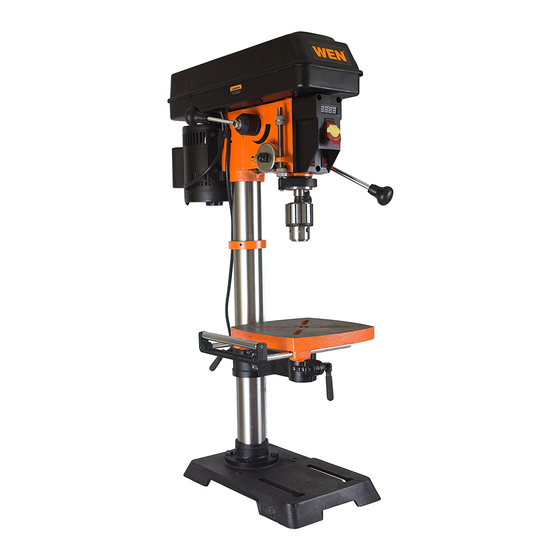
MODEL 4214, 4214T
12" VARIABLE SPEED
DRILL PRESS
Instruction Manual
NEED HELP? CONTACT US!
Have product questions? Need technical support? Please feel free to contact us:
1-800-232-1195 (M-F 8AM-5PM CST)
TECHSUPPORT@WENPRODUCTS.COM
IMPORTANT: Your new tool has been engineered and manufactured to WEN's highest standards for dependability,
ease of operation, and operator safety. When properly cared for, this product will supply you years of rugged,
trouble-free performance. Pay close attention to the rules for safe operation, warnings, and cautions. If you use
your tool properly and for its intended purpose, you will enjoy years of safe, reliable service.
WENPRODUCTS.COM
For replacement parts and the most up-to-date instruction manuals, visit
Advertisement
Table of Contents

Related Manuals for Wen 4214


Summary of Contents for Wen 4214
- Page 1 1-800-232-1195 (M-F 8AM-5PM CST) TECHSUPPORT@WENPRODUCTS.COM IMPORTANT: Your new tool has been engineered and manufactured to WEN’s highest standards for dependability, ease of operation, and operator safety. When properly cared for, this product will supply you years of rugged, trouble-free performance. Pay close attention to the rules for safe operation, warnings, and cautions. If you use your tool properly and for its intended purpose, you will enjoy years of safe, reliable service.
-
Page 2: Table Of Contents
CONTENTS WELCOME Introduction ..................... 3 Specifications ....................3 SAFETY General Safety Rules ..................4 Specific Safety Rules for the Drill Press ............6 Electrical Information ..................8 Know Your Drill Press ..................9 BEFORE OPERATING Assembly & Adjustments ................10 OPERATION & MAINTENANCE Operation ....................... -
Page 3: Welcome
INTRODUCTION Thanks for purchasing the WEN Drill Press. We know you are excited to put your tool to work, but first, please take a moment to read through the manual. Safe operation of this tool requires that you read and understand this operator’s manual and all the labels affixed to the tool. -
Page 4: Safety
GENERAL SAFETY RULES WARNING! Read all safety warnings and all instructions. Failure to follow the warnings and instructions may result in electric shock, fire and/or serious injury. Safety is a combination of common sense, staying alert and knowing how your item works. The term “power tool” in the warnings refers to your mains-operated (corded) power tool or battery-operated (cordless) power tool. - Page 5 GENERAL SAFETY RULES WARNING! Read all safety warnings and all instructions. Failure to follow the warnings and instructions may result in electric shock, fire and/or serious injury. Safety is a combination of common sense, staying alert and knowing how your item works. The term “power tool” in the warnings refers to your mains-operated (corded) power tool or battery-operated (cordless) power tool.
-
Page 6: Specific Safety Rules For The Drill Press
SPECIFIC RULES FOR THE DRILL PRESS WARNING: Do not let comfort or familiarity with the product replace strict adherence to product safety rules. Failure to follow the safety instructions may result in serious personal injury. 1. TOOL PURPOSE. This drill press is designed to drill through metal and wood. Drilling through other materials could result in fire, injury, or damage to the workpiece. - Page 7 SPECIFIC RULES FOR THE DRILL PRESS 12. DRILLING THE WORKPIECE. • Allow spindle to reach full speed before drilling the workpiece. • Never start the machine with the drill bit pressed against the workpiece. • Adjust the table or depth stop to avoid drilling into the table. •...
-
Page 8: Electrical Information
ELECTRICAL INFORMATION GROUNDING INSTRUCTIONS In the event of a malfunction or breakdown, grounding provides the path of least resistance for an electric current and reduces the risk of electric shock. This tool is equipped with an electric cord that has an equipment grounding conductor and a grounding plug. -
Page 9: Know Your Drill Press
KNOW YOUR DRILL PRESS TOOL PURPOSE Drill presses are mainly used to drill clean, precise cylindrical holes into workpieces or enlarge existing holes. You may also find other uses for your drill press such as reaming, countersinking, counterboring, tapping, etc. Refer to the diagram below and on page 10 to become familiarized with the parts and controls of your drill press. -
Page 10: Before Operating
ASSEMBLY & ADJUSTMENTS UNPACKING With the help of a friend or trustworthy foe, carefully remove the drill press from the packaging. Make sure to take out all contents and accessories. Do not discard the packaging until the drill press is completely assembled. - Page 11 ASSEMBLY & ADJUSTMENTS WARNING: If any part is missing or damaged, do not plug the drill press in until the missing or damaged part is repaired or replaced. The column assembly (column, column support, rack, rack collar, and table support bracket) must be attached to the base.
- Page 12 ASSEMBLY & ADJUSTMENTS DRILL PRESS HEAD TO COLUMN (FIG. 5) WARNING: The drill press head is heavy. To avoid injury, two people should lift it into position. 1. Carefully lift the drill press head assembly (Fig. 5 - 1) and position it over the column (Fig.
- Page 13 ASSEMBLY & ADJUSTMENTS MOUNTING THE DRILL PRESS (FIG. 8) The drill press must be securely fastened through the mounting holes (Fig. 8 - 1) to a stand or workbench with heavy-duty fasteners (not included). This will prevent the drill press from tipping over, sliding, or walking during operation.
- Page 14 ASSEMBLY & ADJUSTMENTS REMOVE THE CHUCK (FIG. 10) 1. Turn the feed handles (1) to lower the chuck (2) to the lowest position. 2. Insert the drift key (3) into the opening in the quill. Gently tap on the wedge using a rubber mallet (4) (not included). The chuck and arbor will drop out.
- Page 15 ASSEMBLY & ADJUSTMENTS INSTALL THE TABLE EXTENSION (FIG. 12B) 1. Insert the two rods (Fig. 12B - 1) of the table extension into the two channels (Fig. 12B - 2) at the side of the table. 2. Place a wing knob (Fig. 12B - 3) in the opening on the bottom of each channel and tighten to secure the extension to the table.
- Page 16 ASSEMBLY & ADJUSTMENTS ADJUSTING THE LASER (FIG. 15 & 16) WARNING: Do not stare directly at the laser beam. Observe all safety rules. • Never aim the beam at a person or an object other than the workpiece. • Always make sure the laser beam is aimed at a workpiece that does not have reflective surfaces, as the laser beam could reflect into your eyes or the eyes of others.
- Page 17 ASSEMBLY & ADJUSTMENTS SPINDLE RETURN SPRING (FIG. 17) The spindle is equipped with an auto-return mechanism. The main components are a spring and a notched housing. The spring was properly adjusted at the factory and should not be readjusted unless absolutely necessary.
- Page 18 ASSEMBLY & ADJUSTMENTS DRILL PRESS ON / OFF SWITCH (FIG. 19) 1. To turn the drill press ON, insert the yellow safety key (Fig. 19 - 1) into the switch housing (Fig. 19 - 2). As a safety feature, the switch cannot be turned ON without the safety key.
-
Page 19: Operation & Maintenance
OPERATION GENERAL DRILLING GUIDELINES - DRILLING A HOLE WARNING: To prevent the workpiece and the backup material from slipping from your hand while drilling, position the workpiece and backup material to the left side of the column. If the workpiece and the backup material are not long enough to reach the column, clamp the workpiece and backup material to the table. - Page 20 OPERATION DEPTH SCALE METHOD (FIG. 21B) 1. Make sure the 0 (in or mm) mark on the depth gauge rests at the top edge of the metal support (Fig. 21B - 4) when the quill is fully retracted. 2. Put the workpiece on the table and raise the table until the tip of the drill bit just touches the top of the workpiece.
- Page 21 OPERATION DRILLING METAL • Use metal-piercing twist drill bits. • It is always necessary to lubricate the tip of the drill with oil to prevent overheating of the drill bit. • All metal workpieces should be clamped down securely. Any tilting, twisting, or shifting causes a rough drill hole, and increases the potential of drill bit breakage.
- Page 22 OPERATION DRILL BIT SIZE RECOMMENDATIONS Wood Aluminum, Zinc, Brass Iron, Steel 2000 to 3200 3/8 in. 9.5 mm 7/32 in. 5.6 mm 3/32 in. 2.4 mm 1400 to 2000 5/8 in. 16 mm 11/32 in. 8.75 mm 5/32 in. 4 mm 1000 to 1400 7/8 in.
-
Page 23: Maintenance
WARNING: Any attempt to repair or replace electrical parts on this tool may be hazardous. Servicing of the tool must be performed by a qualified technician. When servicing, use only identical WEN replacement parts. Use of other parts may be hazardous or induce product failure. ROUTINE INSPECTION Before each use, inspect the general condition of the tool. -
Page 24: Troubleshooting Guide
TROUBLESHOOTING WARNING: Stop using the tool immediately if any of the following problems occur. Repairs and replacements should only be performed by an authorized technician. For any questions, please contact our customer service at (800) 232-1195, M-F 8-5 CST or email us at techsupport@wenproducts.com. - Page 25 TROUBLESHOOTING ASSEMBLY & ADJUSTMENTS WARNING: Stop using the tool immediately if any of the following problems occur. Repairs and replacements should only be performed by an authorized technician. For any questions, please contact our customer service at (800) 232-1195, M-F 8-5 CST or email us at techsupport@wenproducts.com.
-
Page 26: Exploded View & Parts List
EXPLODED VIEW & PARTS LIST ASSEMBLY & ADJUSTMENTS 81 84 40 41... - Page 27 EXPLODED VIEW & PARTS LIST ASSEMBLY & ADJUSTMENTS NOTE: Parts may only be available in their respective subassemblies. Not all parts may be available for purchase. PART NO. DESCRIPTION PART NO. DESCRIPTION A - SPINDLE PULLEY ASSEMBLY (PART 4214B-AA) G - CRANK ASSEMBLY (PART 4214B-AG) 4214B-002 4214B-129 Handle...
- Page 28 EXPLODED VIEW & PARTS LIST ASSEMBLY & ADJUSTMENTS PART NO. DESCRIPTION PART NO. DESCRIPTION 4214B-001 Circlip for Shaft, Ø24 4214B-079 Screw M6x8 4214B-080 4214B-006 Cogged V-belt, 10x900 Phillips-Head Screw, M5x8, 4214B-019 Lock Nut, M10 4214B-081 with Spring & Flat Washers 4214B-020 Flat Washer, Ø10 4214B-1128...
-
Page 29: Warranty Statement
GREAT LAKES TECHNOLOGIES, LLC (“Seller”) warrants to the original purchaser only, that all WEN consumer power tools will be free from defects in material or workmanship for a period of two (2) years from date of purchase. Ninety days for all WEN products if the tool is used for professional or commercial use. - Page 30 NOTES...
- Page 31 NOTES...
- Page 32 THANKS FOR REMEMBERING V. 2021.03.25...
Need help?
Do you have a question about the 4214 and is the answer not in the manual?
Questions and answers